I've modeled a 20 Hz TH using a DCS205-4 in Hornresp. It's supposed to have a 50 Hz Low Pass filter as well. I'm not sure what defines a good tapped horn. I've included the parametres and measurements for you experts to have a look at. Please advise if you see something wrong or anything that could be improved.


Looks OK except the segments should be parabolic [PAR]. This will increase S3 a bit, though tuning it so low, you give up a lot of gain in the ~27-40 Hz BW compared to my slightly smaller one.
Also, you inputted the driver’s [Mms] in the [Mmd] field, which alters the specs a bit since [Mmd] will always be < [Mms], so need to let HR calculate it.
Adding at least a 0.5 ohm [Rg] for wiring loss further refines it a bit.
GM
Also, you inputted the driver’s [Mms] in the [Mmd] field, which alters the specs a bit since [Mmd] will always be < [Mms], so need to let HR calculate it.
Adding at least a 0.5 ohm [Rg] for wiring loss further refines it a bit.
GM
Attachments
Oh right, didn't realize about the Mmd.
Was going to make it simpler to build by going conical, but I'll try the parametres you posted and see if I can manage. Your isn't slightly smaller, but significantly smaller, I'd like that.
I'm not sure how to treat a parabolic when building it though. Do I break it up into small sections and then follow the flare?
EDIT: I've found a thread that says that if a rectangular csa is used with 2 parallel and 2 non-parallel walls, it will actually be Parabolic and not conical. So if I set it to Parabolic it simulates closer to real life, and I just build it normally like would have building conical (csa increase at a constant rate over the entire length)?
Last edited:
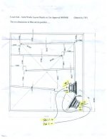
Right, since the driver is ~20.8 cm in diameter [confirm!], then allow a little 'wiggle' room, so make L12 at least 21.5 cm [or more/less if they turn out to be bigger/smaller] and line the edge of the drivers to it, allowing maybe a folded business card's thickness to keep them from physically touching, then use the drivers to mark their mounting holes.
Note that L12 usually needs to be braced and the drivers ideally should be mounted in push-pull and wired to be in-phase.
GM
Note that L12 usually needs to be braced and the drivers ideally should be mounted in push-pull and wired to be in-phase.
GM
Last edited:
Just so we're clear about what you mean by push-pull and wired in phase, they are facing opposite directions, correct? Otherwise they'd be pushing and pulling at the same direction unless I reverse the polarity of one of them.
Thanks for these pointers GM, you've been really helpful.
Thanks for these pointers GM, you've been really helpful.

- Status
- This old topic is closed. If you want to reopen this topic, contact a moderator using the "Report Post" button.
- Home
- Loudspeakers
- Subwoofers
- Tapped Horn query