It is affordable, is extremely simple to build, small, and according to HR simulations the output looks very respectable. Group delay and excursion also look reasonable with the $50 SWE-10S4 drivers that i used in the sims.. .
Tinkering around with Hornresponse a while back i came up with this design... I never built one (and i probably never will because i have already moved on to other ideas that i want to pursue) but i thought i would post this on DIYaudio to see if anyone finds it interesting or useful .. I was also curious to see what the big-brained subwoofer gurus had to say, be it good or bad ..
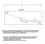
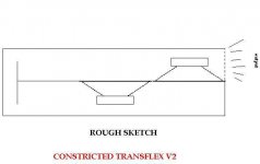
I refer to it as a constricted transflex, but its like a tapped horn that is squeezed down in the middle, and it is also like a pipe-resonance mode based (instead of helmholtz mode) series tuned 6th order bandpass box ..
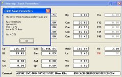
The drivers need to have an FS close to FB, along with tight suspensions and strong motors to work properly in this box...
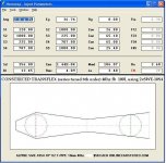
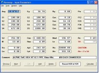
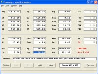
I found two different ways of simulating it in HR, one utilizes the compression chamber function, and the other doesn't , but as far as i can tell both sim methods are valid and produce a very similar response and output ... I will post both sets of HR inputs.
As you can see one of the drivers can be physically mounted in reverse and the phase flipped to make this a push-pull (actually push-push right?) to cancel some distortion.. I know the "PP" feature has been something that some folks on this site have been using lately in other designs, so call me trendy ...
...
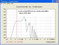
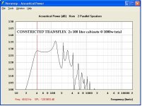
According to sims two of these cabinets (combined total of 200 liters) can handle 1000 watts without pushing the 10S4 drivers past their excursion ratings of 10mm one way, and output should be just under 130db with solid response all the way down to 40hz in halfspace .. Seems great for 2 small boxes that could be built in less than a day, using only 200 dollars worth of drivers total !
In a car or a truck (1/8th space or .5pi) the output is pretty obscene with one cabinet making 135db with only 500 watts input power , but of course only down to 40hz which is fine for much music but not all (depends on your personal preferences right?)
I didn't show any cabinet bracing in the sketch but its easy enough to improvise those ...
The response graphs remind me of some of the old MTL-1X Manifold-horn cabinets that EV used to make for dual 18" woofers, which is not suprising because those were also series tuned 6th order bandpass boxes, only much larger ...
I am looking forward to hearing your thoughts and reading you comments regarding this design.
Tinkering around with Hornresponse a while back i came up with this design... I never built one (and i probably never will because i have already moved on to other ideas that i want to pursue) but i thought i would post this on DIYaudio to see if anyone finds it interesting or useful .. I was also curious to see what the big-brained subwoofer gurus had to say, be it good or bad ..
I refer to it as a constricted transflex, but its like a tapped horn that is squeezed down in the middle, and it is also like a pipe-resonance mode based (instead of helmholtz mode) series tuned 6th order bandpass box ..
The drivers need to have an FS close to FB, along with tight suspensions and strong motors to work properly in this box...
I found two different ways of simulating it in HR, one utilizes the compression chamber function, and the other doesn't , but as far as i can tell both sim methods are valid and produce a very similar response and output ... I will post both sets of HR inputs.
As you can see one of the drivers can be physically mounted in reverse and the phase flipped to make this a push-pull (actually push-push right?) to cancel some distortion.. I know the "PP" feature has been something that some folks on this site have been using lately in other designs, so call me trendy
... According to sims two of these cabinets (combined total of 200 liters) can handle 1000 watts without pushing the 10S4 drivers past their excursion ratings of 10mm one way, and output should be just under 130db with solid response all the way down to 40hz in halfspace .. Seems great for 2 small boxes that could be built in less than a day, using only 200 dollars worth of drivers total !
In a car or a truck (1/8th space or .5pi) the output is pretty obscene with one cabinet making 135db with only 500 watts input power , but of course only down to 40hz which is fine for much music but not all (depends on your personal preferences right?)
I didn't show any cabinet bracing in the sketch but its easy enough to improvise those ...
The response graphs remind me of some of the old MTL-1X Manifold-horn cabinets that EV used to make for dual 18" woofers, which is not suprising because those were also series tuned 6th order bandpass boxes, only much larger ...
I am looking forward to hearing your thoughts and reading you comments regarding this design.
Attachments
-
 Constricted-Transflex--with additional measurements.JPG35.1 KB · Views: 8,272
 -
 2cabs(200L-total_1000w).JPG48.7 KB · Views: 8,122
 -
 Alpine-SWE-10S4-Parameters.jpg52.6 KB · Views: 7,829
 -
 100L-Constricted-Transflex-Inputs-fish.JPG67.8 KB · Views: 7,751
 -
 100L-Constricted-Transflex-Inputs-CHAMBERED.JPG61.2 KB · Views: 7,680
Last edited:
Freddi, Im sure a 12" driver could work in this box, it would definitely fit, but the specs would have to be pretty tight and the FS would need to be higher than most car audio 12s ....
XRK971, I see what you mean ... For the non chambered version the contraction isn't abrupt enough, and the chambered version actually models the first section as just a pipe or a tube with an extremely abrupt constriction .... Two very different shapes for the first section but the sims produce similar results as long as the internal air space and path length of that section are the same (and if the constriction also has the same area).. It seems like the geometry of that section should be having more impact on sims, but its not for some reason ...... Having more segments to work with would allow me to make a more accurate model, maybe i could get someone to sim this in Akabak to confirm that the results are still acceptably good..
XRK971, I see what you mean ... For the non chambered version the contraction isn't abrupt enough, and the chambered version actually models the first section as just a pipe or a tube with an extremely abrupt constriction .... Two very different shapes for the first section but the sims produce similar results as long as the internal air space and path length of that section are the same (and if the constriction also has the same area).. It seems like the geometry of that section should be having more impact on sims, but its not for some reason ...... Having more segments to work with would allow me to make a more accurate model, maybe i could get someone to sim this in Akabak to confirm that the results are still acceptably good..
the 12" 12S4 version has 30Hz fs - how would it fare?
http://support.alpine-usa.com/products/documents/OM_SWA-10S4_SWA-12S4_EN.pdf
that Pioneer 10 looks nice - was one set of spec reversed? saw 1.15 as qt and 0.4-something as vas - http://www.parts-express.com/pionee...-1200w-mobile-audio-subwoofer-4-ohm--267-2501
http://support.alpine-usa.com/products/documents/OM_SWA-10S4_SWA-12S4_EN.pdf
that Pioneer 10 looks nice - was one set of spec reversed? saw 1.15 as qt and 0.4-something as vas - http://www.parts-express.com/pionee...-1200w-mobile-audio-subwoofer-4-ohm--267-2501
Last edited:
Yessir, a 3" gap and outer dimensions of 14"x14"x36" . Those are outside dimensions, already compensated for 1/2" material .... Made with something like a good birch ply would keep it light enough to be easily carried by one person ... You could use thicker material but the outside dimensions would increase slightly... With 1/2" material you could increase to the 14.25" dimensions if you want to make up for the airspace that the internal panel takes up.. Good thinking (thats where you were going with that right?)
Thar PDF you posted is for the SWA series, i was simming with the SWE series drivers ... The specs on the Alpine SWE drivers are more useful in this app ....
The SWE-12S4 is a really good value too, but with the FS being a little lower (36hz) the path length would have to be made a little longer ... I would have to adjust the sim and see how it looks (one 12 per box) .. My guess is that the maximum output would be less but the bass would extend lower, it would be more affordable, but with half the power handling since we would be using only one driver per cab instead of two ...
http://support.alpine-usa.com/products/documents/OM-SWE-10_12_S4.pdf
Last edited:
Freddi,
this place still carries them:
Alpine SWE-10S4 10" 750W 4-Ohm Type-E Series Car Audio Subwoofer at Onlinecarstereo.com
this place still carries them:
Alpine SWE-10S4 10" 750W 4-Ohm Type-E Series Car Audio Subwoofer at Onlinecarstereo.com
mixed reviews on that seller Online Car Stereo - Vernon - Vernon, CA | Yelp
These guys say they have the 10S4s in stock , but i would call to be sure
Alpine Type-E Subwoofer SWE-10S4 | Creative Car Audio
Alpine Type-E Subwoofer SWE-10S4 | Creative Car Audio
and another , price isnt as good as the above link though
Alpine SWE-10S4 10" Type E Series Black Subwoofer SWE10S4
Alpine SWE-10S4 10" Type E Series Black Subwoofer SWE10S4
and another ... but since the supply of these seems to be drying up i might try to seek out some more alternative drivers ..
Alpine SWE-10S4 10" 750W 4 Ohm Type E Series Car Audio Subwoofer
Alpine SWE-10S4 10" 750W 4 Ohm Type E Series Car Audio Subwoofer
Almost, if the FS was a little higher on that one, and the VAS a bit lower ... I just had a look at the parameters listed on the Polk website ...
There is an affordable Pioneer that looks like a marginal candidate , and an Orion that can work ..... So far nothing has quite nailed the specs like the 10S4 does though, i will keep looking ...
There is an affordable Pioneer that looks like a marginal candidate , and an Orion that can work ..... So far nothing has quite nailed the specs like the 10S4 does though, i will keep looking ...
XRK971
I tinkered around with HR a little more to try to approximate the proper shape of the first section and of course it puts the driver too close to the constriction , so even though there really isnt any way that i know of to fully sim this box in Hornresponse i do see that lo-and-behold this shape does shift the FB up by a few hertz ... So good call .. I didn't notice that before ..
I did however come up with a variation that we can fully simulate using the throat chamber function .... Looks like it only loses a db or so, and is still as simple as the other design while still maintaining similar outer dimensions (or even a little smaller) .... It is a little more flexible too and could possibly accommodate a wider variety of drivers since changing the shape and length of "Lpt" and "Ap1" seems to have significant effects upon the response curve..
Extension seems slightly better and the low compression ratio (almost 1:1) should reduce the likelihood of physical damage with the drivers such as cone failure ..
Tell me what you think of this ..
Attachments
Last edited:
- Status
- This old topic is closed. If you want to reopen this topic, contact a moderator using the "Report Post" button.
- Home
- Loudspeakers
- Subwoofers
- New sub design? Constricted Transflex, simple build (series tuned 6th order)