I like the organic looking shape of that lens
Ahh , ok yes , that makes a lot of sense 🙂 Especially when you consider that many of the Eminence models with that rising response have very low Le figures and very light cones extending their response well into the upper mids but those same drivers are still going to be subject to the same physics as any other large driver which demand that the upper mids have an increasingly narrow dispersion as frequency rises........
So I guess that is where our lenses and slots come into play if you have enough power response on the top end to work with...
Oh yes , i am finding that the Karlson concepts are definitely special and interesting (more than our simulations would indicate).
...
Zetta , have you ever seen the old sci-fi classic movie called "Alien"? The small and creepy alien "facehuggers" would emerge from the top of their egg pods through an opening, BUT if they had for whatever reason felt the need to burst out of the sides of their egg pod instead (possibly because that was where the unsuspecting face was located) then i am sure that they would leave a big hole in the side of the egg that would look exactly like that JBL diffraction lens !!!
hehehe


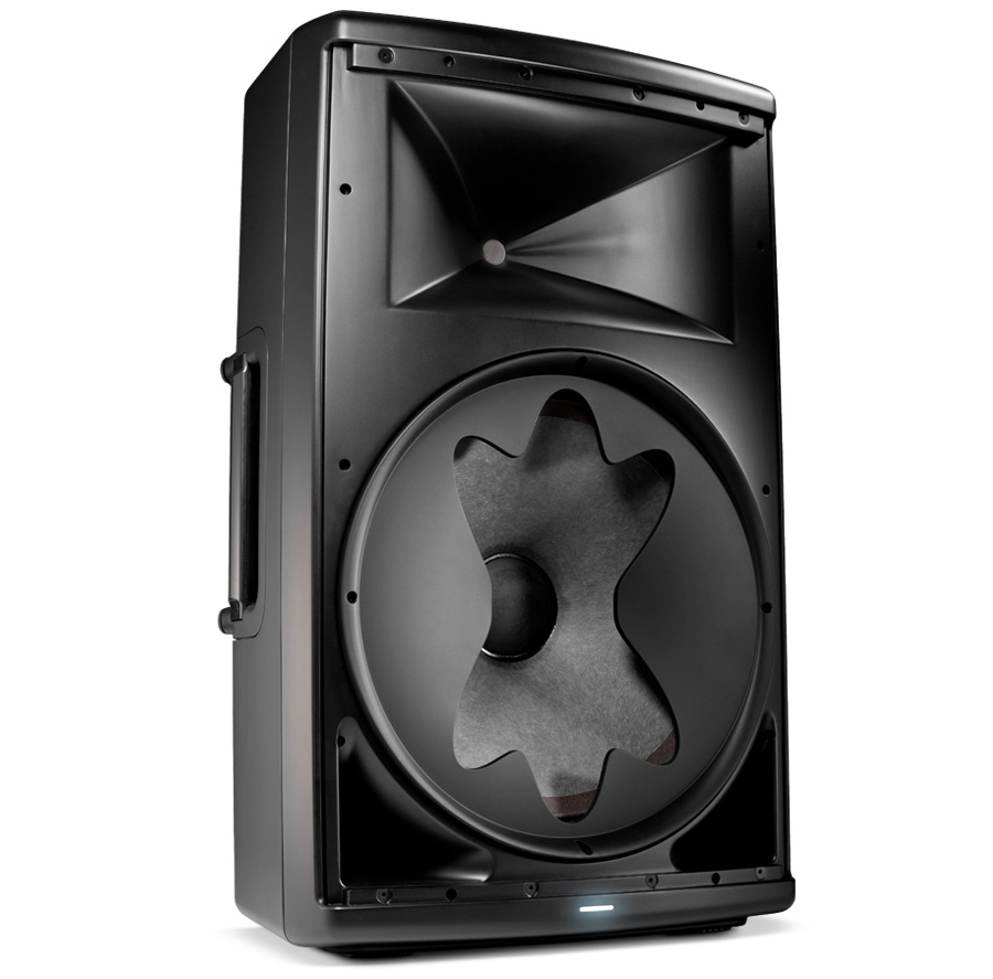
Yeah, JBL has been using the concept for a while. As far as I know, the famous Eminence "rising response" is a symptom of the driver having a reasonably flat power response but narrowing directivity up where the radiator is getting large relative to wavelength. Using a diffraction lens is a way to take that narrowing beamwidth and diffract it to maintain more even coverage.
Ahh , ok yes , that makes a lot of sense 🙂 Especially when you consider that many of the Eminence models with that rising response have very low Le figures and very light cones extending their response well into the upper mids but those same drivers are still going to be subject to the same physics as any other large driver which demand that the upper mids have an increasingly narrow dispersion as frequency rises........
So I guess that is where our lenses and slots come into play if you have enough power response on the top end to work with...
The K-slot is interesting because it is both a diffraction lens and a resonator without a single path length.
Oh yes , i am finding that the Karlson concepts are definitely special and interesting (more than our simulations would indicate).
...
Zetta , have you ever seen the old sci-fi classic movie called "Alien"? The small and creepy alien "facehuggers" would emerge from the top of their egg pods through an opening, BUT if they had for whatever reason felt the need to burst out of the sides of their egg pod instead (possibly because that was where the unsuspecting face was located) then i am sure that they would leave a big hole in the side of the egg that would look exactly like that JBL diffraction lens !!!
hehehe
Zetta , have you ever seen the old sci-fi classic movie called "Alien"? The small and creepy alien "facehuggers" would emerge from the top of their egg pods through an opening, BUT if they had for whatever reason felt the need to burst out of the sides of their egg pod instead (possibly because that was where the unsuspecting face was located) then i am sure that they would leave a big hole in the side of the egg that would look exactly like that JBL diffraction lens !!!
Nice analogy, indeed you could call the Karlflex an Alien Speaker. Definitely a different animal, hehe 😀
Finding a happy medium in the front to rear chamber ratios
Freddi ,
It is hard for me to say because the front chamber/aperture section is the only part that Akabak is not properly modeling or at least not well enough to be considered accurate so after some real-world experiments with the prototype i can only speculate at this point and to me it seems that using a K-slot becomes a good choice if the front chamber is made large enough, and having the wings obscure the sides of the cone is a good thing (with the right driver) and can make your polar response measurements more consistent whether on-axis or off-axis at the expense of some upper midrange output so it is likely worth pursuing if your driver has enough of a rising response to spare to begin with ...
The issue i see with making the front chamber considerably larger is the fact that keeping the same total cabinet size would require that that the rear chamber would in-turn need to be reduced, so some response at the lowest frequencies would be sacrificed in order to improve the midband response, and if taken too far you would end up having an overdamped response with an F3 that is very high, sort of like the graph you attached to post #1579 , as you say "it did not go low" but looks like it would be a super punchy midbass cabinet which can be really useful in some applications (such as part of a big multi-way system as the "Kick Bins"), just not ideal as a stand alone cab for reproducing modern music which is what i have been shooting for......
In my case i think i could probably increase my front/back chamber ratio slightly to improve the midbass response (maybe by increasing the height of the Freddi-mod cavity) but i cannot change the ratio by too much without increasing total cabinet size or i would lose too much output down around the fundamental's vicinity ...
I cannot say for sure if the higher aspect reduces peaking in the front chamber but i CAN say for certain with confidence that using the Freddi-Mod cavity (a stuffed stub as part of the front chamber) definitely does smooth the front chamber's resonances , tames response and generally makes the cabinet more pleasant to listen to .
.

MMJ - could the front chamber be made somewhat deeper and not be wasteful or chaotic in response so a regular warm and fuzzy K-aperture could be retained?
here's an 18" K in my pile - ~41.5"H x 22.5"W x 16D - does a higher aspect tend to limit cavity peaking with low q drivers ?
- it did not "go low", - - there are dips with the mic on the ground - not sure how well it does/did in the listening plane
Freddi ,
It is hard for me to say because the front chamber/aperture section is the only part that Akabak is not properly modeling or at least not well enough to be considered accurate so after some real-world experiments with the prototype i can only speculate at this point and to me it seems that using a K-slot becomes a good choice if the front chamber is made large enough, and having the wings obscure the sides of the cone is a good thing (with the right driver) and can make your polar response measurements more consistent whether on-axis or off-axis at the expense of some upper midrange output so it is likely worth pursuing if your driver has enough of a rising response to spare to begin with ...
The issue i see with making the front chamber considerably larger is the fact that keeping the same total cabinet size would require that that the rear chamber would in-turn need to be reduced, so some response at the lowest frequencies would be sacrificed in order to improve the midband response, and if taken too far you would end up having an overdamped response with an F3 that is very high, sort of like the graph you attached to post #1579 , as you say "it did not go low" but looks like it would be a super punchy midbass cabinet which can be really useful in some applications (such as part of a big multi-way system as the "Kick Bins"), just not ideal as a stand alone cab for reproducing modern music which is what i have been shooting for......
In my case i think i could probably increase my front/back chamber ratio slightly to improve the midbass response (maybe by increasing the height of the Freddi-mod cavity) but i cannot change the ratio by too much without increasing total cabinet size or i would lose too much output down around the fundamental's vicinity ...
does a higher aspect tend to limit cavity peaking with low q drivers ?
I cannot say for sure if the higher aspect reduces peaking in the front chamber but i CAN say for certain with confidence that using the Freddi-Mod cavity (a stuffed stub as part of the front chamber) definitely does smooth the front chamber's resonances , tames response and generally makes the cabinet more pleasant to listen to
.
Last edited:
Freddi gave birth to an alien ;-)
I first saw that movie as a child back in the early 80s, and there were a few parts that made me uneasy (not much else left such an impression), i was probably too young to see it 😛 ...... I really do love all of the H.R. Giger art concepts in it, amazing dark stuff ...
And about our Alien-level weird speaker: I like "different" animals!, i got so tired of seeing the same old animals over and over ...
Sebastian ,
In response to your post #1580 , yes , such a 🤐 balancing act! Right? You can adjust one component to straighten out one part of the spectrum but it just introduces bumps and dips in another part of the spectrum ....
From your script in #1580 I can see that you discovered the useful changes which can occur when adjusting the length of the Freddi-Mod cavity 😀 But once again it is not a perfect solution due to this same balancing act ...... It is almost as if we need two Freddi-Mod chambers with marginally different tunings, one longer, and one shorter (The difference only needs to be 10 to 15 cm between the two tunings , perhaps to damp a few different odd harmonics individually instead of trying to tame both the 5th and 7th with a single cavity) . SO I CAME UP WITH A CRAZY IDEA!
It is possible to split the width of the Freddi-Mod cavity , increase the height , and then make one section longer than the other (the longer cavity simply takes a 90 degree turn behind the shorter cavity) , it is actually extremely simple , including this change in the build is not much more difficult than using a brace in the Freddi-Mod cavity which is something that is suggested anyway (and this divider doubles as a brace😎) ...... In this case the Freddi-Mod section would need to be sketched from the top down ...
I have a feeling you might like this 😀
NOTE: This double Freddi-Mod concept might also be something we could stack (instead of side-by side) so in that case we could fully sketch it from the side view ...
Nice analogy, indeed you could call the Karlflex an Alien Speaker. Definitely a different animal, hehe 😀
I first saw that movie as a child back in the early 80s, and there were a few parts that made me uneasy (not much else left such an impression), i was probably too young to see it 😛 ...... I really do love all of the H.R. Giger art concepts in it, amazing dark stuff ...
And about our Alien-level weird speaker: I like "different" animals!, i got so tired of seeing the same old animals over and over ...
Sebastian ,
In response to your post #1580 , yes , such a 🤐 balancing act! Right? You can adjust one component to straighten out one part of the spectrum but it just introduces bumps and dips in another part of the spectrum ....
From your script in #1580 I can see that you discovered the useful changes which can occur when adjusting the length of the Freddi-Mod cavity 😀 But once again it is not a perfect solution due to this same balancing act ...... It is almost as if we need two Freddi-Mod chambers with marginally different tunings, one longer, and one shorter (The difference only needs to be 10 to 15 cm between the two tunings , perhaps to damp a few different odd harmonics individually instead of trying to tame both the 5th and 7th with a single cavity) . SO I CAME UP WITH A CRAZY IDEA!
It is possible to split the width of the Freddi-Mod cavity , increase the height , and then make one section longer than the other (the longer cavity simply takes a 90 degree turn behind the shorter cavity) , it is actually extremely simple , including this change in the build is not much more difficult than using a brace in the Freddi-Mod cavity which is something that is suggested anyway (and this divider doubles as a brace😎) ...... In this case the Freddi-Mod section would need to be sketched from the top down ...
I have a feeling you might like this 😀
Code:
System 'S1'


|The outer dimensions are 24" H x 20" W x 18.25" D with half-inch ply material

Def_Driver  '15LB100'
  dD=38cm   |Piston
  fs=40.9Hz  Vas=113L  Qms=7.13
  Qes=0.35  Re=5.5ohm  Le=1.4mH  ExpoLe=0.618


System '99L-KARLFLEX'
| vt=99L,  (net)
|Rear Chamber=74L, fB=40Hz,
|Front chamber=25L-ish (roughly 17L+8-ish from the Fredditech-Cavity)


|---------------------------------------------------------
| The speaker or driver :
|---------------------------------------------------------
Driver 'Driver' Def='15LB100' Node=1=0=18=2


|--------------------------------------------
| The first section (S1, S2 , S3 in Hornresponse lingo):
|--------------------------------------------
|S1=F0     (adjusting this waveguide's length adjusts the driver offset)
|P0    (make this half of your driver's diameter)
|S2=Node2  (center of driver's cone)
|s3=F1 (length is = Node2 to the bottom of main vent aka interchamber vent)
|--------------------------------------------------

Waveguide 'F0'
    Node=50=51
    wth=48.3cm hth=8cm
    wmo=48.3cm hmo=8.1cm
    Len=58.8cm
    Conical
    |OFF
    AcouResistance  'Stuffing1'  Node=50=51 Ra=30e3Pas/m3  | Simulate moderate stuffing

Duct 'P0' Node=51=2
WD=48.3cm
HD=25.5cm
Len=19.7cm
VISC=1


Waveguide 'F1'
    Node=2=4
    wth=48.3cm hth=25.5cm
    wmo=48.3cm hmo=25.6cm
    Len=31.5cm
    Conical

|-----------------------------------
|   Parasitic chamber
|-----------------------------------

Duct    'P5'  Node=51=52
    WD=48.3cm  HD=2,5cm  Len=43cm

  Duct    'P6'  Node=52=0
    WD=48.3cm  HD=7,5cm  Len=43cm  Visc=50


      Duct    'P7'  Node=52=53
    WD=48.3cm  HD=2,5cm  Len=43cm

  Radiator  'Rad1'  Def='P7'    Node=53
    x=0  y=0  z=0  HAngle=0  VAngle=0


|---------------------------------------------
| The interchamber vent (connects the rear chamber to the front chamber)
| Be sure to account for some additional effective length if there are
|boundaries near the end of the vent.
|----------------------------------------------

Duct 'P2' Node=4=5
WD=48.3cm
HD=6.3cm
Len=31.1cm
Visc=1


| EXPERIMENTAL CAVITY/DUCT/STUB
| Suggested by Freddi from DIYaudio.com
| This is a very effective method of suppressing the
| upper pipe harmonics and therefore tames and smooths response

Duct 'P3' Node=5=0
WD=24.15cm
HD=10cm
Len=41.3cm
VISC=50

| EXPERIMENTAL CAVITY/DUCT/STUB #2
| Suggested by Freddi from DIYaudio.com
| This is a very effective method of suppressing the
| upper pipe harmonics and therefore tames and smooths response

Duct 'P9' Node=5=0
WD=24.15cm
HD=10cm
Len=25cm
VISC=50


|-----------------------------------------------------------------------------
|  APERTURE STYLE "E" SECTION
|  Simple Front Chamber combined with shallow ML-Transflex style mouth
| Couples end of path with other side of cone's output (aka "Tapped") in
| regards to bass frequencies but not in the upper frequencies allowing
|6th order performance without the bandpass cutoff limitations in bandwidth.
|-----------------------------------------------------------------------------

|
|  The front chamber section (above the driver), nodes reversed for tapered shape.
|
Waveguide 'F2'
    Node=18=5
    wth=48.3cm hth=6.3cm
    wmo=48.3cm hmo=9cm
    Len=31cm
    Conical


|
|  The dimensions and depth of the mouth/aperture(technically also part
|  of the front chamber).
|
Duct 'P4' Node=18=6
WD=48.3cm
HD=40.6cm
Len=2.6cm
VISC=1


Radiator 'Radiator' DEF='P4' Node=6 |Radiator or mouth dimensions defined by P4
Last edited:
HOLY MOLY YOU DID IT
I LOVE YOUR CRAZY IDEA 😀
That is a genius solution. Must admit, that I admire your "problem crushing skills". You really nailed it this time, BRAVO .
.
I LOVE YOUR CRAZY IDEA 😀
That is a genius solution. Must admit, that I admire your "problem crushing skills". You really nailed it this time, BRAVO
.a staggered cavity does sound good - - hey MMJ - I appreciate your insight into my questions on cavity depth and volume vs overall bulk and performance.
Matthew, I have played around a bit with your brilliant idea and came up with this.
Almost got rid of the 420 hz dip 😉
Stacking chamber opens up new doors 🙂... but then an extra divider would be needed. With this script height is 87 cm, which is ok.
Almost got rid of the 420 hz dip 😉
Code:
System 'S1'

|The outer dimensions are 24" H x 20" W x 18.25" D with half-inch ply material

Def_Driver  '15LB100'
  dD=38cm   |Piston
  fs=40.9Hz  Vas=113L  Qms=7.13
  Qes=0.35  Re=5.5ohm  Le=1.4mH  ExpoLe=0.618


System '99L-KARLFLEX'
| vt=99L,  (net)
|Rear Chamber=74L, fB=40Hz,
|Front chamber=25L-ish (roughly 17L+8-ish from the Fredditech-Cavity)


|---------------------------------------------------------
| The speaker or driver :
|---------------------------------------------------------
Driver 'Driver' Def='15LB100' Node=1=0=18=2


|--------------------------------------------
| The first section (S1, S2 , S3 in Hornresponse lingo):
|--------------------------------------------
|S1=F0     (adjusting this waveguide's length adjusts the driver offset)
|P0    (make this half of your driver's diameter)
|S2=Node2  (center of driver's cone)
|s3=F1 (length is = Node2 to the bottom of main vent aka interchamber vent)
|--------------------------------------------------

Waveguide 'F0'
    Node=50=51
    wth=48.3cm hth=8cm
    wmo=48.3cm hmo=8.1cm
    Len=58.8cm
    Conical
    |OFF
    AcouResistance  'Stuffing1'  Node=50=51 Ra=30e3Pas/m3  | Simulate moderate stuffing

Duct 'P0' Node=51=2
WD=48.3cm
HD=25.5cm
Len=19.7cm
VISC=1


Waveguide 'F1'
    Node=2=4
    wth=48.3cm hth=25.5cm
    wmo=48.3cm hmo=25.6cm
    Len=31.5cm
    Conical

|-----------------------------------
|   Parasitic chamber
|-----------------------------------

Duct    'P5'  Node=51=52
    WD=48.3cm  HD=2,5cm  Len=43cm

  Duct    'P6'  Node=52=0
    WD=48.3cm  HD=7,5cm  Len=43cm  Visc=50


      Duct    'P7'  Node=52=53
    WD=48.3cm  HD=2,5cm  Len=43cm

  Radiator  'Rad1'  Def='P7'    Node=53
    x=0  y=0  z=0  HAngle=0  VAngle=0


|---------------------------------------------
| The interchamber vent (connects the rear chamber to the front chamber)
| Be sure to account for some additional effective length if there are
|boundaries near the end of the vent.
|----------------------------------------------

Duct 'P2' Node=4=5
WD=48.3cm
HD=6.3cm
Len=31.1cm
Visc=1


| EXPERIMENTAL CAVITY/DUCT/STUB
| Suggested by Freddi from DIYaudio.com
| This is a very effective method of suppressing the
| upper pipe harmonics and therefore tames and smooths response

Duct 'P3' Node=5=0
WD=24.15cm
HD=8cm
Len=44,6cm
VISC=50

| EXPERIMENTAL CAVITY/DUCT/STUB #2
| Suggested by Freddi from DIYaudio.com
| This is a very effective method of suppressing the
| upper pipe harmonics and therefore tames and smooths response

Duct 'P9' Node=5=0
WD=24.15cm
HD=8cm
Len=22cm
VISC=50


|-----------------------------------------------------------------------------
|  APERTURE STYLE "E" SECTION
|  Simple Front Chamber combined with shallow ML-Transflex style mouth
| Couples end of path with other side of cone's output (aka "Tapped") in
| regards to bass frequencies but not in the upper frequencies allowing
|6th order performance without the bandpass cutoff limitations in bandwidth.
|-----------------------------------------------------------------------------

|
|  The front chamber section (above the driver), nodes reversed for tapered shape.
|
Waveguide 'F2'
    Node=18=5
    wth=48.3cm hth=6.3cm
    wmo=48.3cm hmo=9cm
    Len=31cm
    Conical


|
|  The dimensions and depth of the mouth/aperture(technically also part
|  of the front chamber).
|
Duct 'P4' Node=18=6
WD=48.3cm
HD=40.6cm
Len=2.6cm
VISC=1


Radiator 'Radiator' DEF='P4' Node=6 |Radiator or mouth dimensions defined by P4
Stacking chamber opens up new doors 🙂... but then an extra divider would be needed. With this script height is 87 cm, which is ok.
*CHEESY GRIN*
Thank You Thank You
*graceful bow* *graceful bow*
IT'S MAGIC! 😉


I LOVE YOUR CRAZY IDEA 😀
That is a genius solution. Must admit, that I admire your "problem crushing skills". You really nailed it this time, BRAVO
Thank You Thank You
*graceful bow* *graceful bow*
IT'S MAGIC! 😉
Last edited:
Tasteful resonant coloration , how very avant garde of us *giggle*
You are welcome Freddi. They are just my impressions and all that i observed, and the opinions i formed based on those things so i cannot call it "fact" at this point really, at least not yet, but i think i am finally starting to get a better feel for how these types of boxes work 🙂
The stacked or staggered Freddi-Mod cavities are looking like a great way of increasing front chamber volume while also maintaining a very smooth and flat response ... There will be some coloration (due to the front chamber , just like any of these designs with front chambers) yet it will most likely be a very musical sounding and very tasteful resonant coloration because the resonances are all smoothed over, well controlled and spread around across the spectrum ...
Stacked or staggered cavities can be an option for people who don't mind the extra few panels and a little more complication , but the simple Karlflex will stay simple , as it has decently flat response .... I will post the script again for it along with a simulated response graph when i post the updated (and possibly final) sketch for the simple Karlflex ...
When Sebastian finishes his script and is happy with it then the more complex "Tri-chamber Karflex" version sketch can be drawn from those dimensions 🙂
a staggered cavity does sound good - - hey MMJ - I appreciate your insight into my questions on cavity depth and volume vs overall bulk and performance.
You are welcome Freddi. They are just my impressions and all that i observed, and the opinions i formed based on those things so i cannot call it "fact" at this point really, at least not yet, but i think i am finally starting to get a better feel for how these types of boxes work 🙂
The stacked or staggered Freddi-Mod cavities are looking like a great way of increasing front chamber volume while also maintaining a very smooth and flat response ... There will be some coloration (due to the front chamber , just like any of these designs with front chambers) yet it will most likely be a very musical sounding and very tasteful resonant coloration
because the resonances are all smoothed over, well controlled and spread around across the spectrum ... Stacked or staggered cavities can be an option for people who don't mind the extra few panels and a little more complication , but the simple Karlflex will stay simple , as it has decently flat response .... I will post the script again for it along with a simulated response graph when i post the updated (and possibly final) sketch for the simple Karlflex ...
When Sebastian finishes his script and is happy with it then the more complex "Tri-chamber Karflex" version sketch can be drawn from those dimensions 🙂
Last edited:
Vertical stacking or horizontal staggering?
Sebastian,
I am glad that it is working for you! and yes , with the extra divider and tall chamber it really does increase the height of the box some ...
If you are planning on stacking the Freddi-Mod cavities vertically then you need to go into the script and change the width of those stubs back to the full internal width of the cabinet ..... So instead of WD=24.15 they would need to be WD=48.3 on both duct P3 and duct P9.
Matthew, I have played around a bit with your brilliant idea and came up with this.
Almost got rid of the 420 hz dip 😉
Stacking chamber opens up new doors 🙂... but then an extra divider would be needed. With this script height is 87 cm, which is ok.
Sebastian,
I am glad that it is working for you!
and yes , with the extra divider and tall chamber it really does increase the height of the box some ...If you are planning on stacking the Freddi-Mod cavities vertically then you need to go into the script and change the width of those stubs back to the full internal width of the cabinet ..... So instead of WD=24.15 they would need to be WD=48.3 on both duct P3 and duct P9.
Last edited:
UPDATE on the Crown Drivecore XLS amp
The deal just got sweeter on the Crown Drivecore XLS 1500
Now only $199 from B&H in New York ! With free shipping!
Some other companies are now selling the XLS 2500 for a very tempting price now too 🙂
Crown Audio XLS 1500 DriveCore Stereo Power Amplifier XLS1500
Crown XLS2500 DriveCore Series Power Amp | Musician's Friend
Scripture
Sebastian ,
Ok , i simulated your Tri-chamber Karlflex with the full width vertically stacked dual Freddi-Mod concept (2" or 5cm height per cavity).... ..This one can be sketched from the side view .... Response looks good ..... Let me know what you think of this script:
Here is a graph at 5db per division for extra detail 🙂
Sebastian ,
Ok , i simulated your Tri-chamber Karlflex with the full width vertically stacked dual Freddi-Mod concept (2" or 5cm height per cavity).... ..This one can be sketched from the side view .... Response looks good ..... Let me know what you think of this script:
Code:
System 'S1'


|The outer dimensions are ___" H x 20" W x 18.25" D with half-inch ply material

Def_Driver  '15LB100'
  dD=38cm   |Piston
  fs=40.9Hz  Vas=113L  Qms=7.13
  Qes=0.35  Re=5.5ohm  Le=1.4mH  ExpoLe=0.618


System '99L-KARLFLEX'
| vt=__L,  (net)
|Rear Chamber=__L, fB=40Hz,
|Front chamber=__L-ish (roughly ___L from the Fredditech-Cavity)


|---------------------------------------------------------
| The speaker or driver :
|---------------------------------------------------------
Driver 'Driver' Def='15LB100' Node=1=0=18=2


|--------------------------------------------
| The first section (S1, S2 , S3 in Hornresponse lingo):
|--------------------------------------------
|S1=F0     (adjusting this waveguide's length adjusts the driver offset)
|P0    (make this half of your driver's diameter)
|S2=Node2  (center of driver's cone)
|s3=F1 (length is = Node2 to the bottom of main vent aka interchamber vent)
|--------------------------------------------------

Waveguide 'F0'
    Node=50=51
    wth=48.3cm hth=8cm
    wmo=48.3cm hmo=8.1cm
    Len=58.8cm
    Conical
    |OFF
    AcouResistance  'Stuffing1'  Node=50=51 Ra=30e3Pas/m3  | Simulate moderate stuffing

Duct 'P0' Node=51=2
WD=48.3cm
HD=25.5cm
Len=19.7cm
VISC=1


Waveguide 'F1'
    Node=2=4
    wth=48.3cm hth=25.5cm
    wmo=48.3cm hmo=25.6cm
    Len=31.5cm
    Conical

|-----------------------------------
|   Parasitic chamber
|-----------------------------------

Duct    'P5'  Node=51=52
    WD=48.3cm  HD=2,5cm  Len=43cm

  Duct    'P6'  Node=52=0
    WD=48.3cm  HD=7,5cm  Len=43cm  Visc=40


      Duct    'P7'  Node=52=53
    WD=48.3cm  HD=2,5cm  Len=43cm

  Radiator  'Rad1'  Def='P7'    Node=53
    x=0  y=0  z=0  HAngle=0  VAngle=0


|---------------------------------------------
| The interchamber vent (connects the rear chamber to the front chamber)
| Be sure to account for some additional effective length if there are
|boundaries near the end of the vent.
|----------------------------------------------

Duct 'P2' Node=4=5
WD=48.3cm
HD=6.3cm
Len=31.1cm
Visc=1


| EXPERIMENTAL CAVITY/DUCT/STUB
| Suggested by Freddi from DIYaudio.com
| This is a very effective method of suppressing the
| upper pipe harmonics and therefore tames and smooths response

Duct 'P3' Node=5=0
WD=48.3cm
HD=5cm
Len=45cm
VISC=50

| EXPERIMENTAL CAVITY/DUCT/STUB #2
| Suggested by Freddi from DIYaudio.com
| This is a very effective method of suppressing the
| upper pipe harmonics and therefore tames and smooths response

Duct 'P9' Node=5=0
WD=48.3cm
HD=5cm
Len=25cm
VISC=50


|-----------------------------------------------------------------------------
|  APERTURE STYLE "E" SECTION
|  Simple Front Chamber combined with shallow ML-Transflex style mouth
| Couples end of path with other side of cone's output (aka "Tapped") in
| regards to bass frequencies but not in the upper frequencies allowing
|6th order performance without the bandpass cutoff limitations in bandwidth.
|-----------------------------------------------------------------------------

|
|  The front chamber section (above the driver), nodes reversed for tapered shape.
|
Waveguide 'F2'
    Node=18=5
    wth=48.3cm hth=6.3cm
    wmo=48.3cm hmo=9cm
    Len=31cm
    Conical


|
|  The dimensions and depth of the mouth/aperture(technically also part
|  of the front chamber).
|
Duct 'P4' Node=18=6
WD=48.3cm
HD=40.6cm
Len=2.6cm
VISC=1


Radiator 'Radiator' DEF='P4' Node=6 |Radiator or mouth dimensions defined by P4
Here is a graph at 5db per division for extra detail 🙂
An externally hosted image should be here but it was not working when we last tested it.
WAR OF THE SCRIPTS
Matthew, I have eliminated the 400 dip/peek totally 😉
I use your stacking method ajusted height and lenght.
Duct 'P3' Node=5=0
WD=48.3cm
HD=4cm
Len=49cm
VISC=50
Duct 'P9' Node=5=0
WD=48.3cm
HD=7cm
Len=21cm
VISC=50
I think we are closing in at something very usefull 🙂
Matthew, I have eliminated the 400 dip/peek totally 😉
I use your stacking method ajusted height and lenght.
Duct 'P3' Node=5=0
WD=48.3cm
HD=4cm
Len=49cm
VISC=50
Duct 'P9' Node=5=0
WD=48.3cm
HD=7cm
Len=21cm
VISC=50
Code:
System 'S1'

|The outer dimensions are ___" H x 20" W x 18.25" D with half-inch ply material

Def_Driver  '15LB100'
  dD=38cm   |Piston
  fs=40.9Hz  Vas=113L  Qms=7.13
  Qes=0.35  Re=5.5ohm  Le=1.4mH  ExpoLe=0.618


System '99L-KARLFLEX'
| vt=__L,  (net)
|Rear Chamber=__L, fB=40Hz,
|Front chamber=__L-ish (roughly ___L from the Fredditech-Cavity)


|---------------------------------------------------------
| The speaker or driver :
|---------------------------------------------------------
Driver 'Driver' Def='15LB100' Node=1=0=18=2


|--------------------------------------------
| The first section (S1, S2 , S3 in Hornresponse lingo):
|--------------------------------------------
|S1=F0     (adjusting this waveguide's length adjusts the driver offset)
|P0    (make this half of your driver's diameter)
|S2=Node2  (center of driver's cone)
|s3=F1 (length is = Node2 to the bottom of main vent aka interchamber vent)
|--------------------------------------------------

Waveguide 'F0'
    Node=50=51
    wth=48.3cm hth=8cm
    wmo=48.3cm hmo=8.1cm
    Len=58.8cm
    Conical
    |OFF
    AcouResistance  'Stuffing1'  Node=50=51 Ra=30e3Pas/m3  | Simulate moderate stuffing

Duct 'P0' Node=51=2
WD=48.3cm
HD=25.5cm
Len=19.7cm
VISC=1


Waveguide 'F1'
    Node=2=4
    wth=48.3cm hth=25.5cm
    wmo=48.3cm hmo=25.6cm
    Len=31.5cm
    Conical

|-----------------------------------
|   Parasitic chamber
|-----------------------------------

Duct    'P5'  Node=51=52
    WD=48.3cm  HD=2,5cm  Len=43cm

  Duct    'P6'  Node=52=0
    WD=48.3cm  HD=7,5cm  Len=43cm  Visc=40


      Duct    'P7'  Node=52=53
    WD=48.3cm  HD=2,5cm  Len=43cm

  Radiator  'Rad1'  Def='P7'    Node=53
    x=0  y=0  z=0  HAngle=0  VAngle=0


|---------------------------------------------
| The interchamber vent (connects the rear chamber to the front chamber)
| Be sure to account for some additional effective length if there are
|boundaries near the end of the vent.
|----------------------------------------------

Duct 'P2' Node=4=5
WD=48.3cm
HD=6.3cm
Len=31.1cm
Visc=1


| EXPERIMENTAL CAVITY/DUCT/STUB
| Suggested by Freddi from DIYaudio.com
| This is a very effective method of suppressing the
| upper pipe harmonics and therefore tames and smooths response

Duct 'P3' Node=5=0
WD=48.3cm
HD=4cm
Len=49cm
VISC=50

| EXPERIMENTAL CAVITY/DUCT/STUB #2
| Suggested by Freddi from DIYaudio.com
| This is a very effective method of suppressing the
| upper pipe harmonics and therefore tames and smooths response

Duct 'P9' Node=5=0
WD=48.3cm
HD=7cm
Len=21cm
VISC=50


|-----------------------------------------------------------------------------
|  APERTURE STYLE "E" SECTION
|  Simple Front Chamber combined with shallow ML-Transflex style mouth
| Couples end of path with other side of cone's output (aka "Tapped") in
| regards to bass frequencies but not in the upper frequencies allowing
|6th order performance without the bandpass cutoff limitations in bandwidth.
|-----------------------------------------------------------------------------

|
|  The front chamber section (above the driver), nodes reversed for tapered shape.
|
Waveguide 'F2'
    Node=18=5
    wth=48.3cm hth=6.3cm
    wmo=48.3cm hmo=9cm
    Len=31cm
    Conical


|
|  The dimensions and depth of the mouth/aperture(technically also part
|  of the front chamber).
|
Duct 'P4' Node=18=6
WD=48.3cm
HD=40.6cm
Len=2.6cm
VISC=1


Radiator 'Radiator' DEF='P4' Node=6 |Radiator or mouth dimensions defined by P4
I think we are closing in at something very usefull 🙂

Nice and flat!
I agree , This is really starting to look pretty good!
by the way , check your email when you have a chance 😉
Matthew, I have eliminated the 400 dip/peek totally 😉
I use your stacking method ajusted height and lenght.
I think we are closing in at something very usefull 🙂
I agree , This is really starting to look pretty good!
by the way , check your email when you have a chance 😉
I love software as a guide and absolutely essential design tool but....
Freddi,
I don't think the compared simulations would really do the K-box any justice since Akabak doesn't seem to model the full benefits of the front chamber properly as far as i can tell (not to mention we are talking about Helmholtz VS Quarterwave/Eigenmode based designs, the latter has always worked better for me despite the software simulations saying they should perform just the same, that's my opinion)............................
To be sure i think that measuring the built boxes would be the best way to compare because the virtual comparisons could be misleading .....
how about a comparison to a plain reflex of the same overall volume?
Freddi,
I don't think the compared simulations would really do the K-box any justice since Akabak doesn't seem to model the full benefits of the front chamber properly as far as i can tell (not to mention we are talking about Helmholtz VS Quarterwave/Eigenmode based designs, the latter has always worked better for me despite the software simulations saying they should perform just the same, that's my opinion)............................
To be sure i think that measuring the built boxes would be the best way to compare because the virtual comparisons could be misleading .....
I agree - (someone asked me the difference in spl) btw - does the stacked absorber take up more room than the single cavity implementation ?
with a single cavity at the top- does it make any difference to cant the board?

with a single cavity at the top- does it make any difference to cant the board?
Last edited:
Freddi,I agree - (someone asked me the difference in spl) btw - does the stacked absorber take up more room than the single cavity implementation ?
Generally yes , stacking absorbers will take up some additional vertical space, especially if you want them to add significant volume to the front chamber (some of the extra required vertical space can be contained internally, meaning not necessarily increasing the height of the box) ....
with a single cavity at the top- does it make any difference to cant the board?
Adding a "cant" or tilt to the cavity's panel as shown in your sketch will tune the stub's resonance higher and reduce the amount of volume added to the front chamber ... Tilting the panel the opposite way will tune it's resonance lower ... So it all depends on what you are trying to accomplish ..
Last edited:
... companies are now selling the XLS 2500 for a very tempting price now too 🙂
Crown Audio XLS 1500 DriveCore Stereo Power Amplifier XLS1500
Crown XLS2500 DriveCore Series Power Amp | Musician's Friend
Dog-gonnit Matt - your well-intended public service announcement regarding the XLS 2500 just cost me $299.
- Home
- Loudspeakers
- Subwoofers
- New sub design? Constricted Transflex, simple build (series tuned 6th order)