See subject - does anyone have decent HornResp model of the CV EL36? The actual driver parameters are not important.
Reason? My brother has just purchased two B&C 18TBX100 drivers to use in two old EL36 cabinets and I want to use HornResp to get an idea of what the result might sound like.
Reason? My brother has just purchased two B&C 18TBX100 drivers to use in two old EL36 cabinets and I want to use HornResp to get an idea of what the result might sound like.
not seen it yet - maybe you can model it from this picture
http://www.bitcore.org/stuff/Bass/Cerwin_Vega/schematic.png
http://www.bitcore.org/stuff/Bass/Cerwin_Vega/schematic.png
not seen it yet - maybe you can model it from this picture
http://www.bitcore.org/stuff/Bass/Cerwin_Vega/schematic.png
Yep, I came across that diagram during another search.
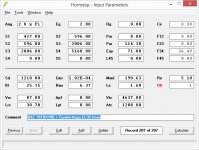
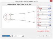
This is what I came up with, based on that diagram. This is the EL36 cabinet with the B&C 18TBX100 18" driver.
Once he has the drivers in, I'll run an impedance test on them to see how close the model matches the real thing. One thing I'm not sure about is if the chamber is stuffed or not - my model has it unstuffed.
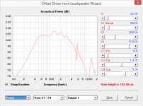
If the model is right - 135dB with about 200W each into 1/4 PI loading (basically two of them along a wall) - oof. And with some DSP to address excursion below 50 Hz or so, that can be raised to 145dB with about 1kW each.
Not too shabby.
Attachments
Probably not a good as this...
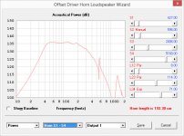
The impedance response of that design shows ripples from 60Hz up which are usually associated with noticeable panel flex that could possibly have an audible effect on the response. Even the lowest peak looks a lot lower than I'd expect. This is probably not a design I'd choose to build, at least in the format indicated. Maybe a few cross-braces along the path and trifurcating the horn, at least for the first half of the path....
- Status
- This old topic is closed. If you want to reopen this topic, contact a moderator using the "Report Post" button.