Hi,
Sealed two LAB12's (6 ohm version) in well stuffed 3.3 cuft would be fine.
The LAB12C needs to be used vented, with its lower Qts than the LAB12.
rgds, sreten.
Hi sreten - So one should not use Parts-Express's recommendation of 0.93ft3 for Lab12? or 1.86ft3 for two of them. If I use 12" sides , which is hardly enough for Lab12, as per tb46's drawing, the internal volume would be 4.4ft3, more than double of PE's figure? Because if one does follow PE's suggestions, Peerless's 830669 @2.4ft3 sealed or Morel MW1075 @2.24ft3 may work better? Needless to say, I have no experience with any of these drivers or how to calculate volume.
Hi toffee123,
Well, as you seem determined to go w/ a corner enclosure:
I have not found a good technical drawing for the LAB12C, so I'm using my old sketch, and even w/ your 12"/12" internal dimensions you have to move the driver forward (thicker baffle) at least 1/2" to make it fit. That may be a good thing, even doubling up (or trippling) on the front baffle w/ 2ea. 3/4" material would not hurt a thing.
With the aspect ratio that develops from using this type of corner box the standard vented enclosure design software will not show the resulting pipe resonances, but Hornresp will. Also, in Hornresp you can design your enclosure as a MLTL (mass-loaded transmission line). I'll attach an example, you can expand on that, the individual dimensions are quite tolerant to being changed, same w/ the damping material.
By the way, I used 50W into 3.11 Ohm in a 1Pi environment, and even then a single driver will give you about 110dB @ 1m. The bottom end diaphragm displacement is easily controlled w/ a 4th order HP set @ 18Hz.
Two of these should give you all the bass you want, a third small sealed sub close to the listener's position might help a lot w/ the room modes.
Regards,
you are right, I like to try out the corner job in my current house. If it worked, then in my new house, I may even sheetrock and paint over it. So hopefully visually it will 'melt' into the background and doesn't take up any space at all.
Moving forward by doubling front baffle is no problem. I must confess that I don't know how to use Hornresp, I feel like a total dumbass and very confused.
Hi toffee123,
Post #21: "... must confess that I don't know how to use Hornresp..."
Welcome to the club. 🙂 All simulation programs seem to have their strong points. I found Hornresp to be relatively easy to get started with, and there are a lot of people here that can help you with specific problems.
Soho54 wrote a nice tutorial over here:
Hornresp for Dum... hmm... Everyone 😉 - Home Theater Forum and Systems - HomeTheaterShack.com
Anyway, watch out for the driver size w/ your corner box.
Regards,
Hi toffee123,
I drew a corner enclosure sketch for the data in Post #18. Then I stretched the box to give your 103" internal height (I took that to mean the distance between a bottom and top board). I entered the new L12 and L23 into Hornresp (no other changes), and was surprised at how nicely that shifted the bottom end of the response downward without messing up the top end. (Bye the way, you only need the triple front baffle where the driver is located, you could taper to double/single layer going away from the driver in both directions.) If I were in the market for a corner enclosure, I'd give one of these two a try. If you do, add some dowel pins to keep the filling in place. Otherwise this is a very straight forward build.
The tilt in the response at the low end is intentional. I think that the port will get more help from the corner than the driver, and there will be some room gain even in your large place.
Regards,
Attachments
-
LAB12_corner_dwg_toffee123_2014_Jun03.pdf33.4 KB · Views: 84
-
 LAB12C_MLTL_Long_2014_Jun03_Input.jpg27.7 KB · Views: 124
 -
 LAB12C_MLTL_Long_2014_Jun03_SPL.jpg20.8 KB · Views: 124
 -
 LAB12C_MLTL_Long_2014_Jun03_Fill.jpg15.5 KB · Views: 120
 -
 LAB12C_MLTL_Long_2014_Jun03_Displacement.jpg19.5 KB · Views: 122
 -
LAB12C_2.txt989 bytes · Views: 55
Hey Oliver, Thanks for your help again. A few thoughts:
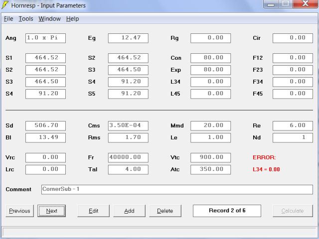
1. We may be using different version of Hornresp? Mine has different interface with more fields:
2. After I downloaded Hornresp and had problem using it, I did reached out to David McBean. He suggested:
I noticed that you were using 1xPi though.
3. Not sure if I am getting it right, I noticed on your drawing that you placed the driver in the middle of the enclosure and have a port or an opening at the bottom? While I really want to try the corner placement, I am not set on sealed box. Just that I thought it would be easily with seal as I don't know how to calculate port etc. with lots of variables.
1. We may be using different version of Hornresp? Mine has different interface with more fields:
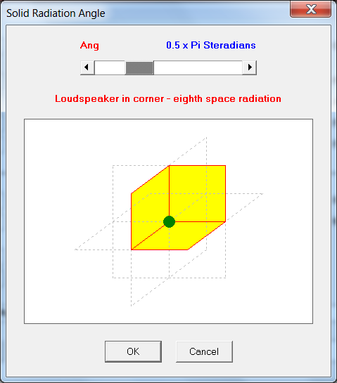
2. After I downloaded Hornresp and had problem using it, I did reached out to David McBean. He suggested:
The speaker system you describe should be simulated in Hornresp as a direct radiator in a closed-box enclosure, radiating into eighth space (0.5 x Pi steradians solid angle) as shown in the attachment. Locating a direct radiator in the corner of a room does not mean that it should be modelled as a horn loudspeaker.
I noticed that you were using 1xPi though.
3. Not sure if I am getting it right, I noticed on your drawing that you placed the driver in the middle of the enclosure and have a port or an opening at the bottom? While I really want to try the corner placement, I am not set on sealed box. Just that I thought it would be easily with seal as I don't know how to calculate port etc. with lots of variables.
Last edited:
Hi toffee123,
Good to see you are tackling Honresp!
To Post #24:
1.: I chopped off the area below the Comment line. See attached example for the Hornresp version I'm using.
2.: I modelled a MLTL (mass-loaded transmission line).
I used 1pi because:
a.) you would have to have very solid walls for 0.5 x Pi corner loading to be effective, e.g.: concrete basement walls and floor. Given modern 2x4 and plaster board construction it is quite unlikely that you would see the full corner boost;
b.) the driver in my MLTL is not located in the bottom corner where three surfaces meet, but at the junction of two surfaces, the port is located in the bottom corner (3 surfaces), and may get more help from the corner than the driver (?). The driver arrangement is OD (Edit/Tools/Driver Arrangement/Offset Driver) for the MLTL, it is Nd (Normal) for a standard sealed or vented enclosure.
3. Yes, driver in the middle, folded port at the bottom; the areas (S1...S5) and distances (L12...L45) are indicated in the sketch. This enclosure w/ the indicated port would be a good starting point for the LAB12C in a corner enclosure.
As to your simulation example: for a sealed box you would use Vrc for the volume, Lrc for the depth of the box, Fr for lining air flow resistivity (density) and Tal for the thickness of the damping material layer. After hitting calculate go to Window/Schematic Diagram and Hornresp will show you a schematic w/ the filling greyed int. A value of 75 to 300 would be for lightly fluffed to denser polyfill (I think).
Hope this helps,
Regards,
I'll attach an example sealed simulation Input screen.
Attachments

Hey Oliver - what about putting the driver towards the ceiling and the port at the bottom or vice verse? Just to take the Allison Boundary effect into consideration? haha the sound would also have to travel the whole 8ft.
Hi toffee123.
Post #26: "... what about putting the driver towards the ceiling and the port at the bottom...?
Just use my Hornresp simulation from Post #23, and change the distances around, e.g.: shorten L12 to 24.14 and lenghten L23 to 224.14. That would move the driver up while leaving the port at the bottom. Don't know what that would sound like in the room, but definitely doable. You would also have to reset the distances from driver to listener, and from port to listener: Calculate/Tools/Output/Combined - in the Combined Acoustical Power window reset the Path length difference.
Regards,
i have not red the whole topic,but designed something i while back for "boatbilder"
see if i can find the related topic.
here it is
see if i can find the related topic.
here it is
Last edited:
- Status
- Not open for further replies.
- Home
- Loudspeakers
- Subwoofers
- Please help a newbie to design/build a pair of corner subs.