I've been working on a folded horn design intended to maximize the use of internal volume in three dimensions as so maximize horn length. It is essentially a cube with seven 90 degree folds. In its simplest form it contains seven chambers. Only the mouth and one of the internal chambers are of increasing cross section along their length. All the rest are constant cross section, however, each is larger than the previous, and the output end of each is larger than the input end. Obviously aspects of this are non-optimal. However, a 3D folded horn is a difficult beast and if some aspects of the simple model can remain, construction is greatly simplified. I'm trying to balance the problems against each other if possible, or find simple additions to the design which can help ameliorate them.
My questions are:
To what extent does a series of straight pipes with outlet always larger than input equate a horn?
Most folded horns I see have rectangular cross sections. This design has several pipes of an assymetrical trapezoid cross section. Might this have an impact?
I'm assuming that the constant cross section segments will be prone to resonances from standing waves. Can these be calculated individually and the dimensions adjusted so they present peaks at different frequencies, or will the many turns and expanding mouth smear them back out? Also, several chambers are a wall thickness away from a different chamber. Might there be any conduction through the walls that might affect (for better or worse) those in the other chamber?
Finally, most folded horns have sharp bends (some with a small baffle at an angle to smooth the bend slightly). Would it be of any use, either with respect to resonance problems or just the transmission in general, for the bends to be curved?
Plans of the simplest design to follow. Note that no correction is made here for wall thickness, etc. This is simply for modeling purposes.
The box is a cube of 24" on a side. The shell is then six pieces of 24" x 24", one of which has a square cut out from one corner, 16" on a side. (fig. 1) The cut out piece is the "front".
One internal baffle (vertical) is 12" x 24". The other (horizontal starts as a 16" x 24" rectangle and has a notch cut from a 24" side so that that edge goes from the original corner to a point midway along that side but only 12" from the other long side, then back to the other original corner. (fig 2).
The only other piece is a side wall for the mouth, 12" in height on one end, 16" on the other, and 13" wide. (fig 3)
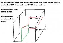
Build the main part of the box, bottom sides and back, using 24" squares. Install the vertical baffle inside the "left" wall, 12" from the back. Install two blocks on the inside of the back wall, 12" from the bottom, and one block on the inside of the "right" wall just at the "front" edge, 16" from the bottom. Set the horizontal baffle on the blocks. Place the mouth side wall under the diagonal edge of the horizontal baffle, touching the inside vertical edge of the vertical baffle and coming to the front edge of the bottom piece. Attach all loose parts. (fig 4)
Put the "front" piece on the box so that the mouth opening is on the bottom right, with the 16" cut edges mating with the front edge of the horizontal baffle and mouth side wall. Attach and seal all internal edges. With the last 24" square placed on top, the box is complete. But don't because it needs a driver.
The driver compartment is front bottom left. The driver can be installed facing up or on another baffle fitting inside this compartment at an angle, making this compartment also expanding. It could also be placed through the mouth side wall in the manner of a tapped horn. The sound path starts here and goes up, then front left to right across the upper half of the front. Here it
turns towards the back along the right wall (an expanding compartment), turns left across the back, then down along the back left edge to the bottom. It then turns right across the bottom of the back, to the bottom right and comes forward through the mouth. Internal path length through the centers of the compartments is approximately 7 feet. Expansion is (cross section of driver compartment = 120 in^2; cross section of mouth = 256 in^2) 2.13, approximately half of which (1.53) occurs at the mouth compartment.
Keep in mind this was conceived as a way of maximizing use of internal area in the smallest total volume. It was not designed from an acoustic standpoint. This project was intended to produce the design then see what could be done to maximize performance. Of course that will in part depend on the intended use of the speaker, which obviously includes driver selection. Also, this seems to better suited to subwoofer use than the full range as it was intended. I'd prefer to resolve the issues from that standpoint, but I'm already convinced this is where it might find better acceptance and use.
This design was actually built and tested using an SAS Bazooka 12". No filter or cross over was used. The garage door 150 feet across the street was rattling. Power was provided by an Audiosource AMP100 bridged to 160 watt mono and running at 100 watts. The impact was unexpectedly good. The tonal quality however was not impressive. This is what I'd like to tweak, with your help. Theoretical assertions are welcome as long as they're stated as such, and same for opinions. But if you make saw dust, your input is particularly appreciated.
My questions are:
To what extent does a series of straight pipes with outlet always larger than input equate a horn?
Most folded horns I see have rectangular cross sections. This design has several pipes of an assymetrical trapezoid cross section. Might this have an impact?
I'm assuming that the constant cross section segments will be prone to resonances from standing waves. Can these be calculated individually and the dimensions adjusted so they present peaks at different frequencies, or will the many turns and expanding mouth smear them back out? Also, several chambers are a wall thickness away from a different chamber. Might there be any conduction through the walls that might affect (for better or worse) those in the other chamber?
Finally, most folded horns have sharp bends (some with a small baffle at an angle to smooth the bend slightly). Would it be of any use, either with respect to resonance problems or just the transmission in general, for the bends to be curved?
Plans of the simplest design to follow. Note that no correction is made here for wall thickness, etc. This is simply for modeling purposes.
The box is a cube of 24" on a side. The shell is then six pieces of 24" x 24", one of which has a square cut out from one corner, 16" on a side. (fig. 1) The cut out piece is the "front".
One internal baffle (vertical) is 12" x 24". The other (horizontal starts as a 16" x 24" rectangle and has a notch cut from a 24" side so that that edge goes from the original corner to a point midway along that side but only 12" from the other long side, then back to the other original corner. (fig 2).
The only other piece is a side wall for the mouth, 12" in height on one end, 16" on the other, and 13" wide. (fig 3)
Build the main part of the box, bottom sides and back, using 24" squares. Install the vertical baffle inside the "left" wall, 12" from the back. Install two blocks on the inside of the back wall, 12" from the bottom, and one block on the inside of the "right" wall just at the "front" edge, 16" from the bottom. Set the horizontal baffle on the blocks. Place the mouth side wall under the diagonal edge of the horizontal baffle, touching the inside vertical edge of the vertical baffle and coming to the front edge of the bottom piece. Attach all loose parts. (fig 4)
Put the "front" piece on the box so that the mouth opening is on the bottom right, with the 16" cut edges mating with the front edge of the horizontal baffle and mouth side wall. Attach and seal all internal edges. With the last 24" square placed on top, the box is complete. But don't because it needs a driver.
The driver compartment is front bottom left. The driver can be installed facing up or on another baffle fitting inside this compartment at an angle, making this compartment also expanding. It could also be placed through the mouth side wall in the manner of a tapped horn. The sound path starts here and goes up, then front left to right across the upper half of the front. Here it
turns towards the back along the right wall (an expanding compartment), turns left across the back, then down along the back left edge to the bottom. It then turns right across the bottom of the back, to the bottom right and comes forward through the mouth. Internal path length through the centers of the compartments is approximately 7 feet. Expansion is (cross section of driver compartment = 120 in^2; cross section of mouth = 256 in^2) 2.13, approximately half of which (1.53) occurs at the mouth compartment.
Keep in mind this was conceived as a way of maximizing use of internal area in the smallest total volume. It was not designed from an acoustic standpoint. This project was intended to produce the design then see what could be done to maximize performance. Of course that will in part depend on the intended use of the speaker, which obviously includes driver selection. Also, this seems to better suited to subwoofer use than the full range as it was intended. I'd prefer to resolve the issues from that standpoint, but I'm already convinced this is where it might find better acceptance and use.
This design was actually built and tested using an SAS Bazooka 12". No filter or cross over was used. The garage door 150 feet across the street was rattling. Power was provided by an Audiosource AMP100 bridged to 160 watt mono and running at 100 watts. The impact was unexpectedly good. The tonal quality however was not impressive. This is what I'd like to tweak, with your help. Theoretical assertions are welcome as long as they're stated as such, and same for opinions. But if you make saw dust, your input is particularly appreciated.
Attachments
1) The closer the series of pipes equate to the horn expansion ratio, the better, but for bass horns three or four straight (non expanding) sections is often enough.1)To what extent does a series of straight pipes with outlet always larger than input equate a horn?
2) This design has several pipes of an assymetrical trapezoid cross section. Might this have an impact?
3) I'm assuming that the constant cross section segments will be prone to resonances from standing waves. Can these be calculated individually and the dimensions adjusted so they present peaks at different frequencies, or will the many turns and expanding mouth smear them back out?
4)Also, several chambers are a wall thickness away from a different chamber. Might there be any conduction through the walls that might affect (for better or worse) those in the other chamber?
5) Would it be of any use, either with respect to resonance problems or just the transmission in general, for the bends to be curved?
6)This design was actually built and tested using an SAS Bazooka 12".
That said, expansion can be designed in to most shapes, just takes a little head scratching and re-setting your saw blade to accomplish.
2) Shape does not matter much as long as the cross sectional area remains the same and the aspect ratio of the shape is not too high.
3) Resonances of sections probably can be calculated using Hornresp or Akaback.
4) The design should be adequately braced so wall members do not vibrate and resonate. Wall vibration can impart a ringing sound, and wastes upper output level.
5) Curved bends are helpful for high frequencies, which behave similar to beams of light (ray tracing) but actually waste valuable cabinet space in a sub 200 Hz (or so) cabinet, as low frequencies tend to flow in a laminar fashion.
6) The raw response of the speaker will be reflected in the output of the horn.
"Sub" type speakers are not appropriate for full range use, and folded horns designed for full range (or even up to 500 Hz) have different design consideration than subs.
Rattling (resonating) garage doors is fairly easy, getting a smooth response from a folded horn is more difficult. Sometimes small physical changes (which can't be simulated) can make fairly large acoustic changes. If you plan to make a good sounding cabinet, having some decent measurement tools (in addition to trained hearing) and learning how to use them will speed up the process quite a bit.
Art
I think the answer to each of your questions is essentially the same...Is the section/dimension etc. significantly smaller than a wavelength at the upper working frequencies of the horn.
Of the horn? You mean the entire internal length?
1) The closer the series of pipes equate to the horn expansion ratio, the better, but for bass horns three or four straight (non expanding) sections is often enough.
That said, expansion can be designed in to most shapes, just takes a little head scratching and re-setting your saw blade to accomplish.
2) Shape does not matter much as long as the cross sectional area remains the same and the aspect ratio of the shape is not too high.
3) Resonances of sections probably can be calculated using Hornresp or Akaback.
4) The design should be adequately braced so wall members do not vibrate and resonate. Wall vibration can impart a ringing sound, and wastes upper output level.
5) Curved bends are helpful for high frequencies, which behave similar to beams of light (ray tracing) but actually waste valuable cabinet space in a sub 200 Hz (or so) cabinet, as low frequencies tend to flow in a laminar fashion.
6) The raw response of the speaker will be reflected in the output of the horn.
"Sub" type speakers are not appropriate for full range use, and folded horns designed for full range (or even up to 500 Hz) have different design consideration than subs.
Rattling (resonating) garage doors is fairly easy, getting a smooth response from a folded horn is more difficult. Sometimes small physical changes (which can't be simulated) can make fairly large acoustic changes. If you plan to make a good sounding cabinet, having some decent measurement tools (in addition to trained hearing) and learning how to use them will speed up the process quite a bit.
Art
1 - In the one I built the notch in the horizontal baffle was smaller than described on the piece over the driver compartment, and larger than described over the rear, rather a bit of plywood sculpturing. I expect to do more.
2 - The compartment for the driver is the only really odd shaped section, nearly triangular.
3 --\I have a learning curve ahead of me. Or the need for more help.
4 - With the baffles firmly attached along all walls, the box is quite solid. Also, I typically attach odd shaped scraps in random places and orientations to break up wall resonance.
5 - I've used self-adhesive floor tiles for bends and can get bends of 2" radius. Helpful? Harmful? Useless?
6 - Absolutely a xover will be used, selected to match the box and driver.
I have an analog SPL meter with a jack so I can lock it in a box and run a wire out, to measure response in the sealed cab. It's not the best, but I always take several measurements at each freq, average them and test them for variance.
Might this design be used as a tapped horn? Placing the driver in the wall of the driver compartment, facing out? If so, might it also be possible to mate two drivers there, face to face and out of phase, for an isobaric driver? An isobaric requires only half the internal volume. Does the reverse hold (ie. does an isobaric driver on a given box make it effectively double the volume)?
5) Curved bends are helpful for high frequencies, which behave similar to beams of light (ray tracing) but actually waste valuable cabinet space in a sub 200 Hz (or so) cabinet, as low frequencies tend to flow in a laminar fashion.5 - I've used self-adhesive floor tiles for bends and can get bends of 2" radius. Helpful? Harmful? Useless?
6-Might this design be used as a tapped horn?
7-Placing the driver in the wall of the driver compartment, facing out?
8-If so, might it also be possible to mate two drivers there, face to face and out of phase, for an isobaric driver?
9-An isobaric requires only half the internal volume. Does the reverse hold (ie. does an isobaric driver on a given box make it effectively double the volume)?
The enclosed area behind self-adhesive floor tiles would be "squishy" like a balloon, not good.
6) Tapped horns can be pretty much any shape and layout.
7) A TH does not use a driver compartment, one side of the driver is near the mouth, the other near the throat.
8) Reverse polarity clam shell isobaric pairs have been used in all types of sub enclosures.
9) It takes displacement to make SPL, an isobaric pair has only the same displacement as one speaker.
An isobaric pair requires approximately half the internal volume to achieve the same low frequency cut off, but uses twice the power (and drivers) to achieve that. Doubling the enclosure volume would increase sensitivity, but would still be less sensitive than the drivers used individually.
In designing any horn enclosure maximizing the use of all internal space is important, and generally expanding sections are preferable.
5) Curved bends are helpful for high frequencies, which behave similar to beams of light (ray tracing) but actually waste valuable cabinet space in a sub 200 Hz (or so) cabinet, as low frequencies tend to flow in a laminar fashion.
The enclosed area behind self-adhesive floor tiles would be "squishy" like a balloon, not good.
6) Tapped horns can be pretty much any shape and layout.
7) A TH does not use a driver compartment, one side of the driver is near the mouth, the other near the throat.
8) Reverse polarity clam shell isobaric pairs have been used in all types of sub enclosures.
9) It takes displacement to make SPL, an isobaric pair has only the same displacement as one speaker.
An isobaric pair requires approximately half the internal volume to achieve the same low frequency cut off, but uses twice the power (and drivers) to achieve that. Doubling the enclosure volume would increase sensitivity, but would still be less sensitive than the drivers used individually.
In designing any horn enclosure maximizing the use of all internal space is important, and generally expanding sections are preferable.
Not responding to some does not mean I'm ignoring them, rather just my acceptance. Thanks, in each case.
7 - The driver compartment is just my terminology, as it can be configured various ways. It is the first pipe and thus the throat. It shares the side wall with the mouth.
9 - I'm not after SPL necessarily, but rather improving response. Power and drivers I have many. What I was asking after I found in the Wikipedia article on isobarics: "The two drivers operating in tandem exhibit exactly the same behavior as one loudspeaker in twice the cabinet". However, "if a speaker is optimized for performance in a 40 liter enclosure, one iso-group of the same speakers can achieve the same low frequency extension and overall response characteristics in a 20 liter enclosure." So were I to use an iso-pair I should use drivers optimized for an enclosure of 453 liters (16 cubic feet)? If so, it seems I'm better off sticking with a single driver. I have some that will do 8 cu ft, but none that will do 16, and fit in the space allowed.
I have no idea how you got from 20 liters to 453 liters, or how you are figuring what the optimum enclosure size should be, but an optimum TH design will use a different enclosure size than a BR or sealed cabinet for the same low cut-off frequency.However, "if a speaker is optimized for performance in a 40 liter enclosure, one iso-group of the same speakers can achieve the same low frequency extension and overall response characteristics in a 20 liter enclosure." So were I to use an iso-pair I should use drivers optimized for an enclosure of 453 liters (16 cubic feet)? If so, it seems I'm better off sticking with a single driver. I have some that will do 8 cu ft, but none that will do 16, and fit in the space allowed
At any rate, if you want to achieve any goal, you need to define what the goal is.
I have no idea how you got from 20 liters to 453 liters, or how you are figuring what the optimum enclosure size should be, but an optimum TH design will use a different enclosure size than a BR or sealed cabinet for the same low cut-off frequency.
At any rate, if you want to achieve any goal, you need to define what the goal is.
The quoted material was referenced as coming from the Wikipedia article, including the 20/40 liter example. The 453 is twice the volume of the design I presented, that being calculated from the volume of the box * 2, as per the example. And the goal was stated in the original post -- to start with the design intended to maximize the use of space, and then attempt to maximize performance with that design. I had assumed that a TH would be considered a vented design.
Dennis,And the goal was stated in the original post -- to start with the design intended to maximize the use of space, and then attempt to maximize performance with that design. I had assumed that a TH would be considered a vented design.
Your original post does not mention TH, nor does it show speaker position, or exit, or horn path, making it difficult to understand what type of design it is.
Vented designs are known as BR (bass reflex), a Helmholtz resonator.
Front loaded horns (FLH) use a compression chamber.
TH and FLH use a path that expands from throat to mouth.
"Maximize performance" is not a goal unless "performance" is specified in terms of efficiency, SPL, frequency response, distortion and anything else important to you.
A design for maximum output from 30-120 Hz and one designed for 50-150 or smooth response from 50-500 Hz are all different goals and would require different designs (and drivers) to achieve.
Using the free software program Hornresp you could model various designs using the same cabinet volume and speaker parameters and decide which fits your version of "maximum performance".
Art
Last edited:
Dennis,
Your original post does not mention TH, nor does it show speaker position, or exit, or horn path, making it difficult to understand what type of design it is.
Vented designs are known as BR (bass reflex), a Helmholtz resonator.
Front loaded horns (FLH) use a compression chamber.
TH and FLH use a path that expands from throat to mouth.
"Maximize performance" is not a goal unless "performance" is specified in terms of efficiency, SPL, frequency response, distortion and anything else important to you.
A design for maximum output from 30-120 Hz and one designed for 50-150 or smooth response from 50-500 Hz are all different goals and would require different designs (and drivers) to achieve.
Using the free software program Hornresp you could model various designs using the same cabinet volume and speaker parameters and decide which fits your version of "maximum performance".
Art
Art,
The original post does not mention TH, this is true. My follow up question does. The original does specify the location of the "driver compartment" and states various mounting configurations could be used. It also specifically states, though does not show in illustration (something beyond my simple graphics capability in 3D perspective drawing) exactly what the horn path is, including the start of the throat ("horn compartment") and the mouth described by name.
The type of design is not specified for the simple reasons this design is intended to start with the geometry and then try to optimize it by alterations to the geometry as well as selection of the specific design, including driver selection and matching to the other variables. I am trying to design a minimally sized cabinet
with maximum use of internal space, in order to provide the smallest speaker with maximal response. That response should of course include aspects of all the variables you mention. I hope to do for this geometry what is done for most designs, which is to achieve the best balance of those variables. As such, my "goal" is to find the best set of parameters this design is capable of, even including altering the geometry -- just as long as it remains the best possible response that a minimal sized cabinet can achieve.
One of my original questions was whether multiple constant cross section pipes with larger outlet than inlet equate to "expanding from throat to mouth" (ie. providing the same or similar acoustic impedance matching as a path with increasing cross section pipes). This is an example of the very basic level I am attempting to start from in order to determine what design (TH, BR, etc.) is possible to use, and provides the best platform for other alterations and considerations. I realize this is not the "traditional" method of optimizing a given speaker, and so does not lend itself to selecting first what parameter to optimize. My goal, if it fits the definition, is to get the most out of the maximized use of internal space, not matter how many other aspects I have to incorporate into the design, which to forego (sealed box vs. TH for example), and how to balance each against the others in order to find the best possible way to use the design.
I apologize if my intention was not clearly stated. It is obviously a starting point far upstream of that in most designs. To my mind, the complexity and the unusual aspects of it make it something that make it not likely to be modeled well by such as hornresp. Seven pipes, five of what are constant cross section and two expanding, but with the openings and cross section from one to the next getting larger each time, and with seven 90 degree bends -- is hornresp capable of this. I've tried it and I can't tell because of this complexity (including possible resonances of various constant cross section chambers).
Bottom line, I'm trying to start with a particular internal geometry and get the most out of it, so I can see if I can come up with the smallest box with the best response for its size. There are a great many things to be balanced here. I'm just trying to figure out which are most important and so where to start.
Again, you have not defined a target response- "maximal" regarding a frequency response and output level must be determined.Art,
I am trying to design a minimally sized cabinet with maximum use of internal space, in order to provide the smallest speaker with maximal response.
As such, my "goal" is to find the best set of parameters this design is capable of, even including altering the geometry -- just as long as it remains the best possible response that a minimal sized cabinet can achieve.
My goal, if it fits the definition, is to get the most out of the maximized use of internal space, not matter how many other aspects I have to incorporate into the design, which to forego (sealed box vs. TH for example), and how to balance each against the others in order to find the best possible way to use the design.
To my mind, the complexity and the unusual aspects of it make it something that make it not likely to be modeled well by such as hornresp. Seven pipes, five of what are constant cross section and two expanding, but with the openings and cross section from one to the next getting larger each time, and with seven 90 degree bends -- is hornresp capable of this.
Bottom line, I'm trying to start with a particular internal geometry and get the most out of it, so I can see if I can come up with the smallest box with the best response for its size.
A simple two fold TH would have maximal upper response, to go low requires more folds to achieve the longer path length needed.
Hoffman's Iron Law applies to all types of sub designs- loud, low, small, pick two. You get to decide what is "best".
Last I checked (been a while and David adds features frequently)Hornresp can model four separate horn segments. Generally the bend can be considered part of a horn segment, but more accurately modeled as a separate part.
If you want to model more parts, you can go to Akaback, and add bits and pieces to your hearts content.
At any rate, the fold pattern presented in the OP seem overly complicated, it seems neither to maximize the use of space or materials.
Is there a reason you want a cubical enclosure?
Again, you have not defined a target response- "maximal" regarding a frequency response and output level must be determined.
A simple two fold TH would have maximal upper response, to go low requires more folds to achieve the longer path length needed.
Hoffman's Iron Law applies to all types of sub designs- loud, low, small, pick two. You get to decide what is "best".
Last I checked (been a while and David adds features frequently)Hornresp can model four separate horn segments. Generally the bend can be considered part of a horn segment, but more accurately modeled as a separate part.
If you want to model more parts, you can go to Akaback, and add bits and pieces to your hearts content.
At any rate, the fold pattern presented in the OP seem overly complicated, it seems neither to maximize the use of space or materials.
Is there a reason you want a cubical enclosure?
Thanks for sticking with me.
No, I am not defining a target response. There are many possible. I want to try to determine what can be done for each (re: Hoffman's Iron Law), including a fourth -- shall we say clarity? Sharpness? whatever. And then from within the design attempt to maximize the response based on getting the best possible combination.
Hoffman is wrong. You don't pick two. You pick two to try to maximize and either ignore, or try to at least to not do something counter productive with the third. Otherwise it's a plain crap shoot. And I say there's four, not three, and I intend to try to pick and work with all four to get the best possible combination of them.
And I agree, Akaback is the better choice. The bends are where the expansion is and they all need to be accounted for.
The original design is intended to maximize horn length in the most compact form possible because I have to move these things around (requiring space in the truck) and set them up in order to play. Sometimes stage space is quite limited. The "overly complicated" structure is an attempt to to *minimize* the use of material (thus weight; but I do believe that's what you meant). How many other 7+ foot horns require less than a full 4' * 8' sheet of material?
Cubic? Not necessarily. There are probably far more efficient uses of space. The best built from pieces of commonly available materials would probably entail approximating a logrithmic spiral (ie. snail shell shaped) in the manner of an expanding buckytube, built from increasing sizes of equilateral triangles. Everything else would fall in between. And if this were an available choice among possibilities, there would be yet another trade off to make between internal geometry type and the other aspects,.per Hoffman. But in the end, I want something that can actually be built, be reasonably light and compact, and give the best sound I can get within those constraints.
When I did my dissertation research I was told I could get either temporal, spatial or frequency resolution on my EEG recordings, pick two. I picked continuous wavelet transform analysis, got all three, and made a movie of cortical responses that occurred to auditory stimuli only in the prefrontal cortex at 2 msec resolution from 20 to 120 msec, and made the first movie of the dopamine system in action. I learned analysis of functional MRI from the guy who invented it and decried its severe limitations (a statistical technique that made it almost certainly bogus in many cases). He said I could maximize localization or field strength, but not both. I chose tensor calculus as a nonlinear method of analyzing the data and got both. I don't know enough yet about how to analyze the design I'm proposing, but I do know enough to know, as so aptly stated in Clarke's First Law: : "When a distinguished but elderly scientist states that something is possible, he is almost certainly right. When he states that something is impossible, he is very probably wrong." I tend towards the impossible and ask that those on whose shoulders I stand only help how they can with what they know so that I may see farther. On the obverse I ask only that those who can't, accept that fact, and don't tell me I can't.
Last edited:
There are an infinite amount of possible target responses from just one loudspeaker and a given amount of material.No, I am not defining a target response. There are many possible. I want to try to determine what can be done for each (re: Hoffman's Iron Law), including a fourth -- shall we say clarity? Sharpness?
How many other 7+ foot horns require less than a full 4' * 8' sheet of material?
Narrowing the target response makes achieving a goal possible.
Designs for subs using TH or TQWP designs using over 7 feet of path length with one four x 8 are fairly common.
The very popular SS15 (single sheet 15) TH is bit shorter length, trading LF extension for upper output.
It trades low drive level efficiency for reduced maximum output and increased distortion.
All cabinet decisions need to be done with a specific "weighting", comparing the ranking in importance between the major metrics of 1- size/weight, 2-efficiency, 3-maximum output level,4-frequency extension, 5-smoothness in and out of passband, 6-distortion, 7-impulse/phase response,8-cost.
All eight (there could be further distinctions made, or other qualities bringing the count much higher) metrics have a direct impact on the others.
As you found in your research it is possible to get both temporal, spatial and frequency resolution on EEG recordings, while without a continuous wavelet transform analysis only two of the three are available.
Made me think back to the mid-1990s when using the IBVA (Interactive Brain Visualisation Analyzer) you could see a continuous waterfall plot of brain wave frequency, amplitude, and duration.
With a bit of experience interpreting the three metrics displayed you could identify individuals by their patterns, and also detect whether they were listening or formulating a response, or talking.
Still, the IBVA was not detailed enough to tell you in the least what someone was actually thinking.
Once you become familiar with the relationship of the different metrics and decide what weighting to give each of them, the cabinet choices will become fewer, as it will require a specific design to maximally satisfy the metric "code" you prefer.
You might use your continuous wavelet transform analysis recordings to determine what metrics correlate with your EEG response the most when listening to subs with widely differing response types.
Art
Last edited:
Good point, and since the OP has not decided bandwidth, very important in the upper range where a long narrow horn may only be 30 degrees or so.One design parameter not mention is dispersion pattern at the output and at a distance used for the typical listener location. Horns gain acoustical efficiency in using a very directed wavefront; quite a bit different from some of the other box alignments.
Tapped horns and FLH do have quite a bit more directivity in the upper bass range than a bass reflex cabinet.
The radiation pattern from a tapped horn is different than a bass reflex cabinet.
Actual measurements in this post:
http://www.diyaudio.com/forums/subwoofers/184982-tapped-horn-directivity.html
The BR cabinet was basically omnidirectional within about 1 dB to 60 Hz, then looses about 3 dB off axis at 125, and around 7 dB at 160 Hz.
The FLH C-horn is basically omnidirectional within about 3 dB to 60 Hz, then looses about 7 dB at 125 Hz, and above. The C-horn has a smaller frontal area than the BR cabinet, the horn is obviously affecting dispersion, not just panel size.
The Keystone TH is basically omnidirectional within about 2 dB to 60 Hz, then looses about 12 dB at 125, and around 9 dB at 160 Hz.
The radiation from the front and back of the cone are imparting a different dispersion at upper frequencies, a different effect than the BR and FLH, which both seem to just narrow more at upper frequencies.
As you said, "quite a bit different".
Art
- Status
- This old topic is closed. If you want to reopen this topic, contact a moderator using the "Report Post" button.
- Home
- Loudspeakers
- Subwoofers
- 3D Folded Horn Design