Hi,
I'm starting this thread as a build blog for a small subwoofer. At the moment I have a pair of small two way speakers so there's room for improvement with the deeper bass.
A local magazine Hobby Hifi had a plan for a subwoofer with a TangBand W8-670C element. The element was in a sell out, €30 a piece and the project was called "Sub aus dem Portokasse": a sub with the postal money, meaning a very low price. Now there's a newer version of the element available W8-670Q, and I though to build this thing up.
I'm trying to be loyal to the idea of the project, so I'll be building a subwoofer with so less money spent as possible, using things that I have in my household. And that's going to be plenty as I am a bit of a DIY enthusiast, both audio and otherwise. I'll be tracking spent money and time in my posts. I'll be accounting everything I buy that could be used in this project to this project, so if I happen to buy a new power tool, the project price will skyrocket. I doubt that to happen, but there most certainly will be some expendables to buy, like blades, drill bits etc.
So, what do I need: the element of course. In oaudio.de web shop they have it, and some black screws as well to bolt the element and plate amp to the case. Oh, and they carry soldering iron tips for my iron, so one of those as well. And then postage. So:
1 TangBand W8-670: €42.00
1 Bag of screws (25 pieces): €2.00
1 Soldering iron tip: €2.50
+ Postage: €5.00
Total: €51.50
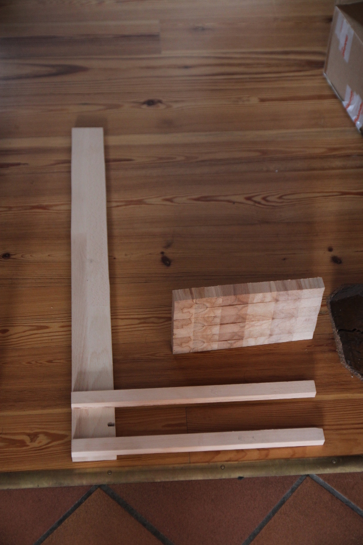
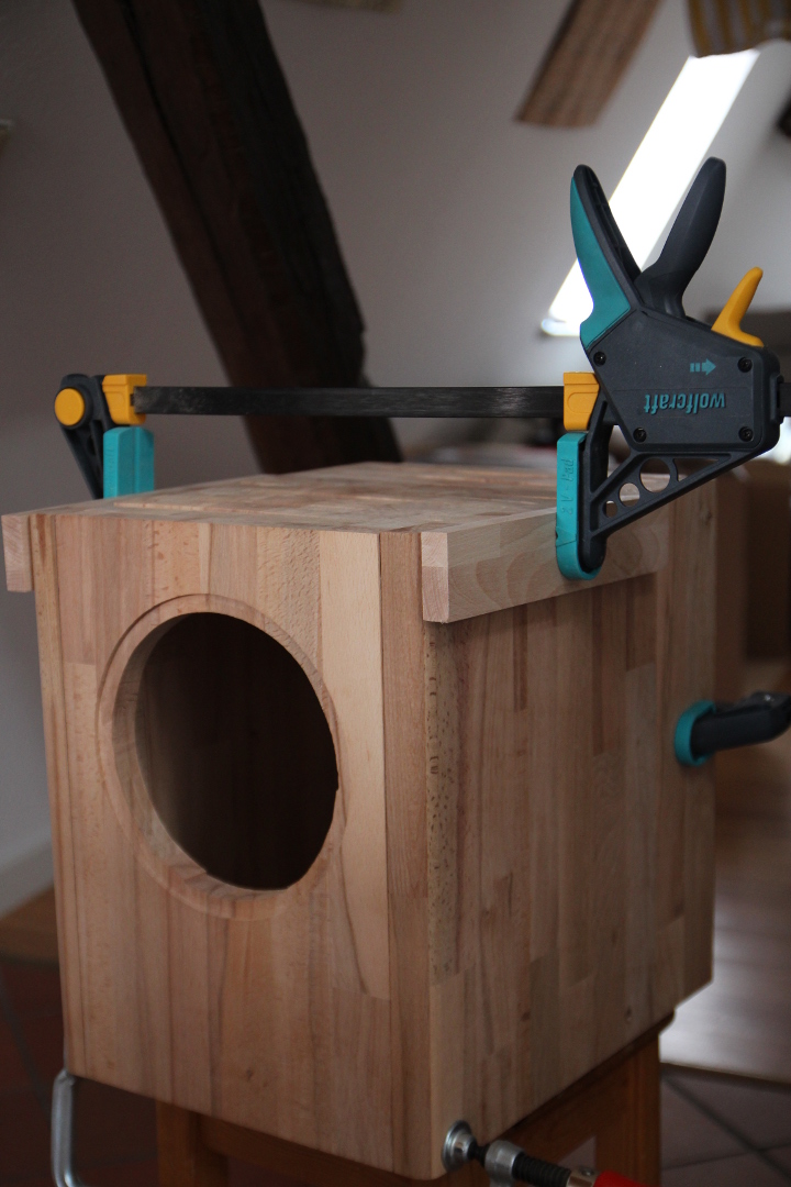
Ok, the building will be mostly the case. But hey, I have wood in my flat! These are leftovers from my just finished bed, 27 mm beech boards. The taller parts are 40 cm tall, which is exactly the desired height of the enclosure. What a luck!
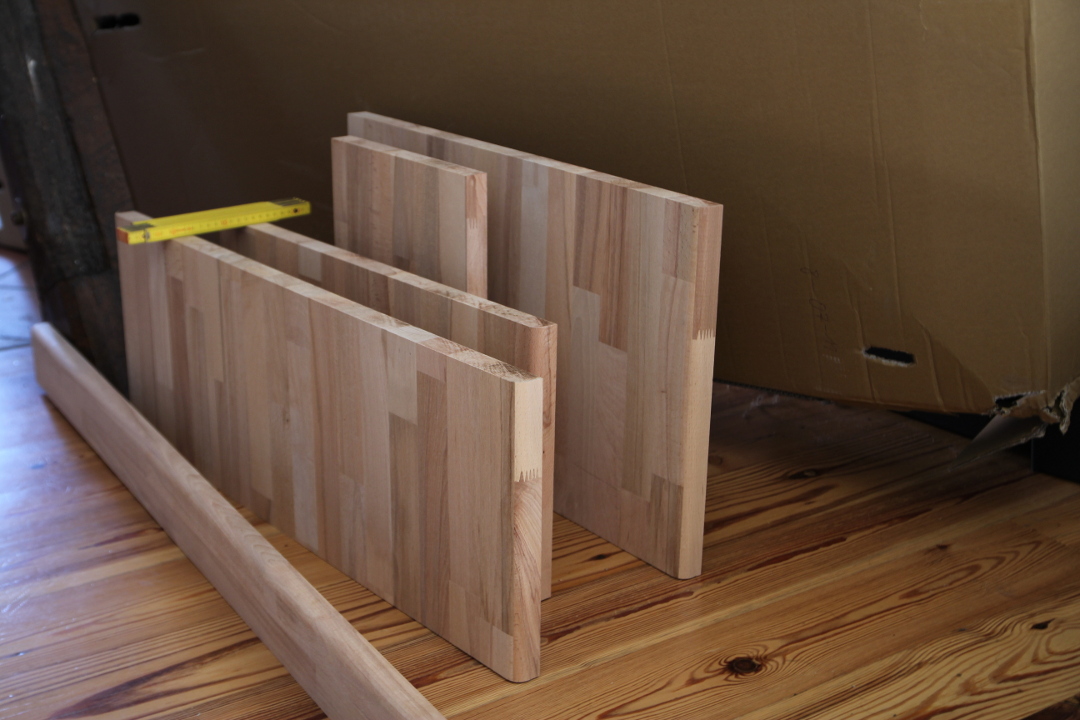
The narrower one is 8mm too wide for the inner width of the front plate. So some work is needed there. The wider is not enough for the both sides, so I decided to cut an extra piece from the long strip to be glued as the front corner as I'd like to use the rounded edges as the front corners.
And then came the first problems.
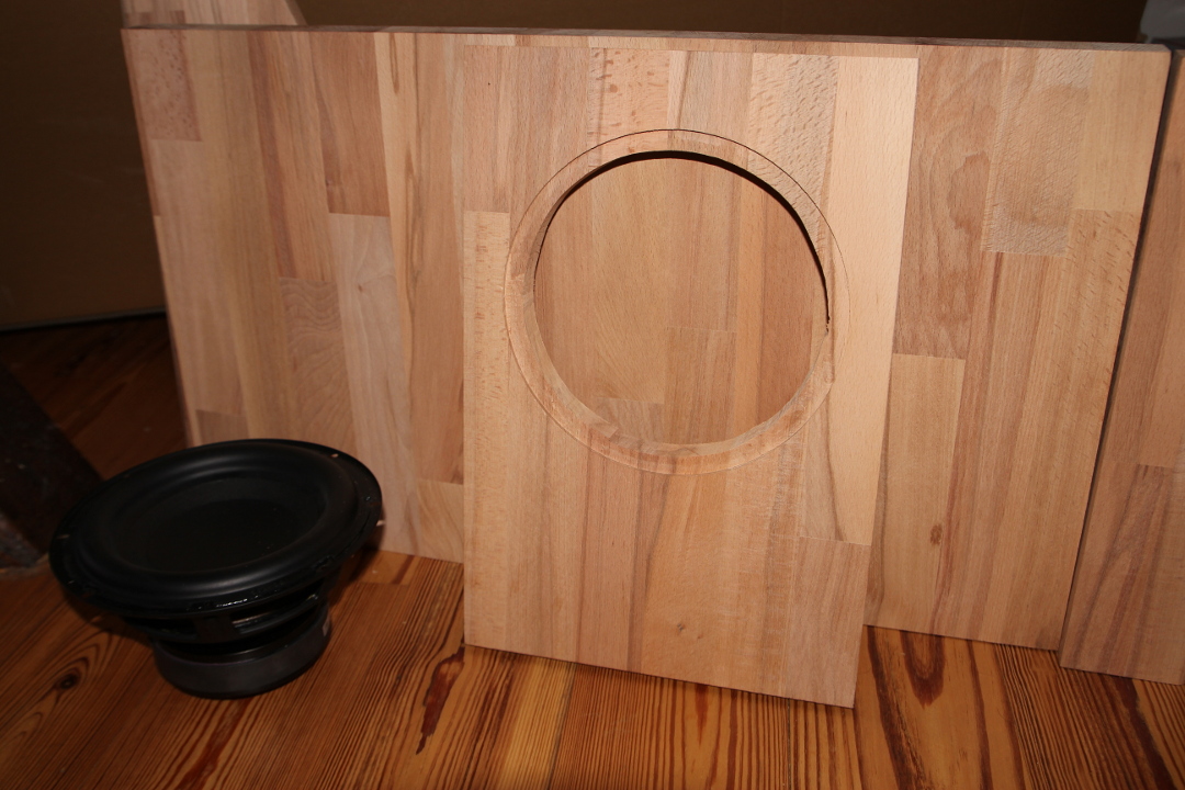
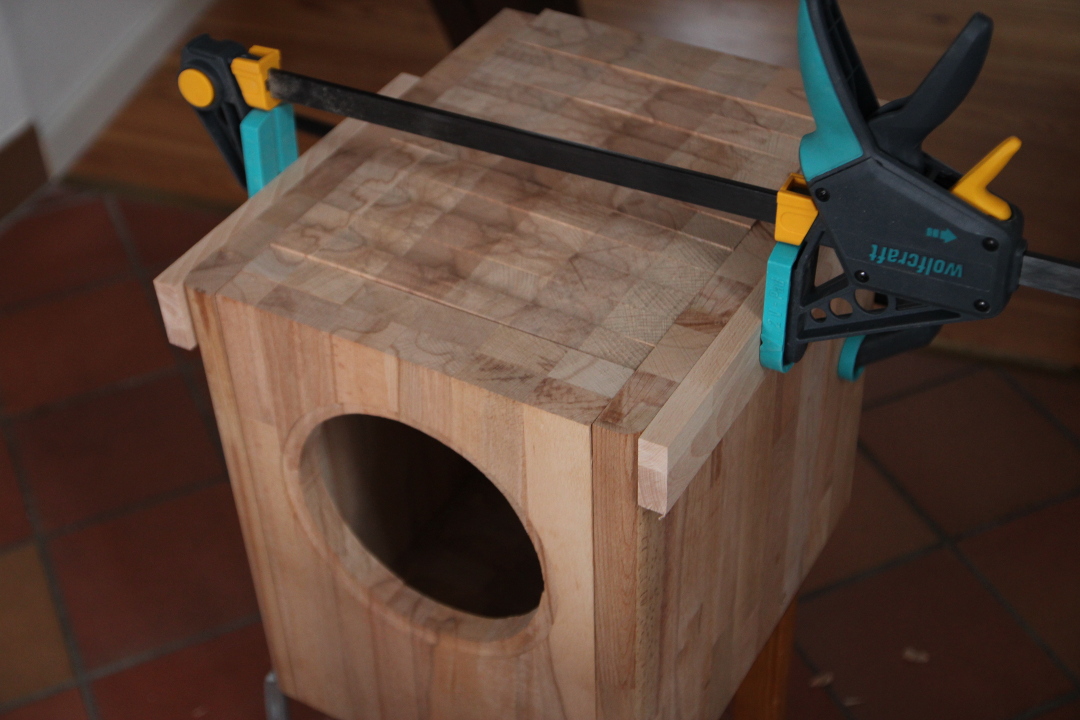
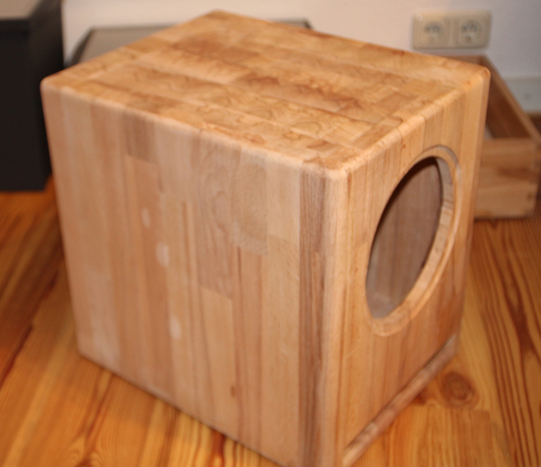
I was thinking to use a wide bit in my router to make a recess for the element. But I barely could get a 21 cm circle with the smallest bit. So I worked with it, drilled a couple of holes together and used my power jigsaw to cut out a piece and chiseled off the wood between the cutout and recess.
And the next problem: the long strip and the board I was thinking for the sides are originally cut from two different boards. So they are machined with tolerances. And here I have now one bigger plate which is 27.4 mm and the smaller piece which is 26.8 mm. So both namely 27 mm but still slightly off. I don't have a power planer so working that off by hand would be too hard in a big plane like that.
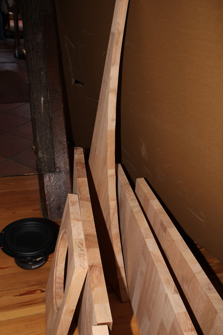
And the board for the sides is a bit warped, and in the wrong direction if I'd use the rounded corner: the warping would tear out the corners. But I still have one bigger piece left over with a circular carving, which I was planning to throw out. So now it could save the project as it is cut out from the same board as the piece for the sides. So I have a bit more work ahead.
I call that a day. The project status so far is:
Money spent: €51.50
Time spent: 3 hours (not counting writing this down.)
I'm starting this thread as a build blog for a small subwoofer. At the moment I have a pair of small two way speakers so there's room for improvement with the deeper bass.
A local magazine Hobby Hifi had a plan for a subwoofer with a TangBand W8-670C element. The element was in a sell out, €30 a piece and the project was called "Sub aus dem Portokasse": a sub with the postal money, meaning a very low price. Now there's a newer version of the element available W8-670Q, and I though to build this thing up.
I'm trying to be loyal to the idea of the project, so I'll be building a subwoofer with so less money spent as possible, using things that I have in my household. And that's going to be plenty as I am a bit of a DIY enthusiast, both audio and otherwise. I'll be tracking spent money and time in my posts. I'll be accounting everything I buy that could be used in this project to this project, so if I happen to buy a new power tool, the project price will skyrocket. I doubt that to happen, but there most certainly will be some expendables to buy, like blades, drill bits etc.
So, what do I need: the element of course. In oaudio.de web shop they have it, and some black screws as well to bolt the element and plate amp to the case. Oh, and they carry soldering iron tips for my iron, so one of those as well. And then postage. So:
1 TangBand W8-670: €42.00
1 Bag of screws (25 pieces): €2.00
1 Soldering iron tip: €2.50
+ Postage: €5.00
Total: €51.50
Ok, the building will be mostly the case. But hey, I have wood in my flat! These are leftovers from my just finished bed, 27 mm beech boards. The taller parts are 40 cm tall, which is exactly the desired height of the enclosure. What a luck!
The narrower one is 8mm too wide for the inner width of the front plate. So some work is needed there. The wider is not enough for the both sides, so I decided to cut an extra piece from the long strip to be glued as the front corner as I'd like to use the rounded edges as the front corners.
And then came the first problems.
I was thinking to use a wide bit in my router to make a recess for the element. But I barely could get a 21 cm circle with the smallest bit. So I worked with it, drilled a couple of holes together and used my power jigsaw to cut out a piece and chiseled off the wood between the cutout and recess.
And the next problem: the long strip and the board I was thinking for the sides are originally cut from two different boards. So they are machined with tolerances. And here I have now one bigger plate which is 27.4 mm and the smaller piece which is 26.8 mm. So both namely 27 mm but still slightly off. I don't have a power planer so working that off by hand would be too hard in a big plane like that.
And the board for the sides is a bit warped, and in the wrong direction if I'd use the rounded corner: the warping would tear out the corners. But I still have one bigger piece left over with a circular carving, which I was planning to throw out. So now it could save the project as it is cut out from the same board as the piece for the sides. So I have a bit more work ahead.
I call that a day. The project status so far is:
Money spent: €51.50
Time spent: 3 hours (not counting writing this down.)
It has been more than a month from the first post. There was a pause while I was a couple of weeks out of country, but I had about a week to do stuff before that and now I have returned back to the project as well.
I did speak to a carpenter friend of mine already before this project started about building a speaker from wood as opposed to MDF or similar. There's an extra difficulty: the grain of wood. As I live in a temperate climate with seasons, the wood will react to the differences in the moisture, but that won't happen in the direction of the grain. So if I glue pieces together with the grain not parallel, I get problems when length of the glued surface is about 10 cm (4") or more. In the end something would crack. There are some techniques to counter that but those aren't airtight, something I'd like to my speaker case to be.
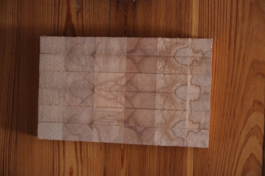
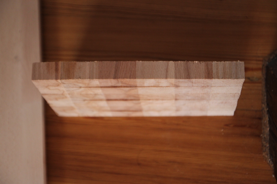
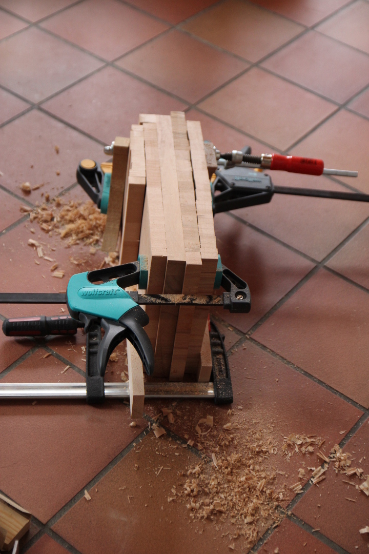
So the only option is to build the speaker so that the grain is in one direction only. So I'll have a lot of sawing to do for the top and bottom plates. And anything with the same orientation. But I'll do get a nice wood pattern on top as I choose the strips by hand:
I made a jig to make the sawing easier with my jigsaw:
It did help, but this wasn't the most ideal solution. (A table saw would be that...) The jig, while it keeps the saw in line, allows it to twist. So from the other angle the result looks like this:
I'll have a lot to even out there. As said, buying new power tools is not an option, but I learned that the local Bauhaus has power tools for rent. So I'll go rent a power planer when I have all the plates glued. I already popped in there to get some more wood for the inner structure and the back plate. I took €12.90 to get some more beech which I had sawed to the right width.
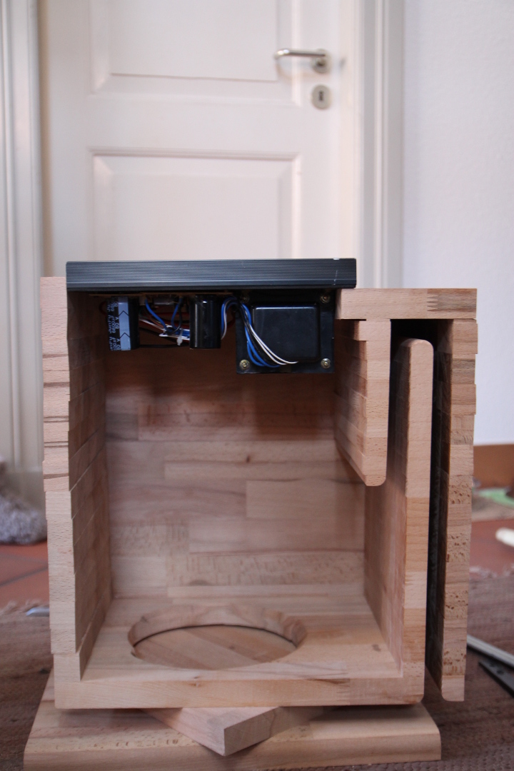
What I'm still missing is the electronics. So it's time to dive into the closet... There's an old plate amp from a previous sub, a Simex BA-480 as it was known in Finland. Internationally it could be better known by its product number in the Part-Express catalog where is was also sold: 300-794.
Well, I could have done the previous steps in another order. I found out that I'm not going to need that much back plate at all when using this plate amp which is bigger than the one used in the magazine as can be seen from this picture with my amp sitting on the planned back plate...
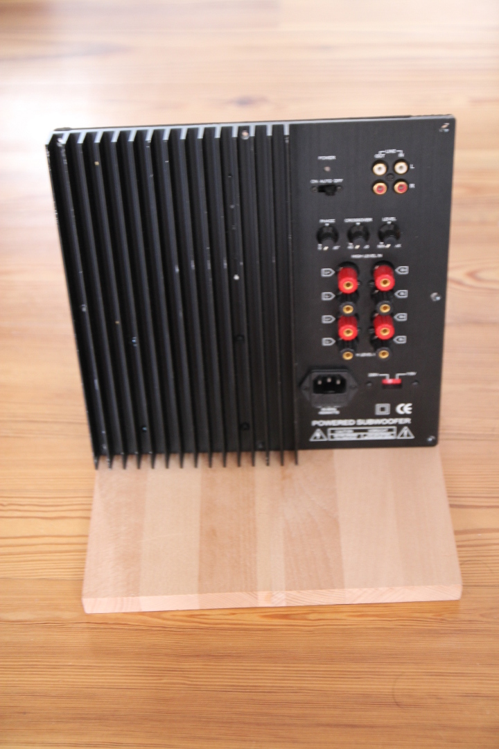
Duh. Now I'll continue with the woodwork and I'll back to the amp later on.
Money spent: €64.40
Time spent: 12 hours
I did speak to a carpenter friend of mine already before this project started about building a speaker from wood as opposed to MDF or similar. There's an extra difficulty: the grain of wood. As I live in a temperate climate with seasons, the wood will react to the differences in the moisture, but that won't happen in the direction of the grain. So if I glue pieces together with the grain not parallel, I get problems when length of the glued surface is about 10 cm (4") or more. In the end something would crack. There are some techniques to counter that but those aren't airtight, something I'd like to my speaker case to be.
So the only option is to build the speaker so that the grain is in one direction only. So I'll have a lot of sawing to do for the top and bottom plates. And anything with the same orientation. But I'll do get a nice wood pattern on top as I choose the strips by hand:
I made a jig to make the sawing easier with my jigsaw:
It did help, but this wasn't the most ideal solution. (A table saw would be that...) The jig, while it keeps the saw in line, allows it to twist. So from the other angle the result looks like this:
I'll have a lot to even out there. As said, buying new power tools is not an option, but I learned that the local Bauhaus has power tools for rent. So I'll go rent a power planer when I have all the plates glued. I already popped in there to get some more wood for the inner structure and the back plate. I took €12.90 to get some more beech which I had sawed to the right width.
What I'm still missing is the electronics. So it's time to dive into the closet... There's an old plate amp from a previous sub, a Simex BA-480 as it was known in Finland. Internationally it could be better known by its product number in the Part-Express catalog where is was also sold: 300-794.
Well, I could have done the previous steps in another order. I found out that I'm not going to need that much back plate at all when using this plate amp which is bigger than the one used in the magazine as can be seen from this picture with my amp sitting on the planned back plate...
Duh. Now I'll continue with the woodwork and I'll back to the amp later on.
Money spent: €64.40
Time spent: 12 hours
So, I have been doing a lot of sawing and gluing. Now I have all the parts for the enclosure about ready. I tried some hand planing for the edges of the plates, it proved to be quite laborious. So next week I'll go pick up the power planer, as the big surfaces need a lot more planing than the edges.
So the side cross-section will look like this:

So the port will be integrated into the enclosure. Here are the parts:
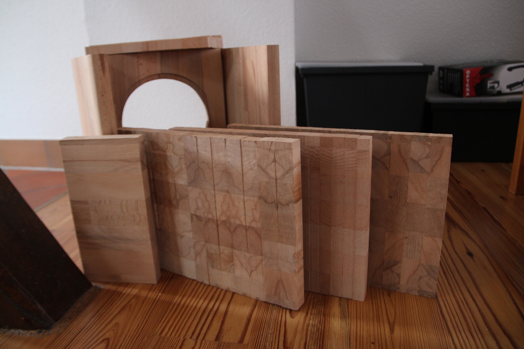
The front row from the left: the back plate (the lower part, rest of it will be covered by the amp), the top plate, the big port part, the bottom plate. In the back row are the sides and the front plate and the little port part on top of those. I chose to take a thicker piece to be the back plate as I still had enough of it for what's left under the amp.
The inner parts came pretty nice when sawed with the power jig saw. The top plate has a lot of planing as the thicker plate takes more toll when the saw twists. Therefore I decided to saw the bottom plate pieces by hand.
Labor, labor, labor is the bill.
Money spent: €64.40
Time spent: 19 hours
So the side cross-section will look like this:
So the port will be integrated into the enclosure. Here are the parts:
The front row from the left: the back plate (the lower part, rest of it will be covered by the amp), the top plate, the big port part, the bottom plate. In the back row are the sides and the front plate and the little port part on top of those. I chose to take a thicker piece to be the back plate as I still had enough of it for what's left under the amp.
The inner parts came pretty nice when sawed with the power jig saw. The top plate has a lot of planing as the thicker plate takes more toll when the saw twists. Therefore I decided to saw the bottom plate pieces by hand.
Labor, labor, labor is the bill.
Money spent: €64.40
Time spent: 19 hours
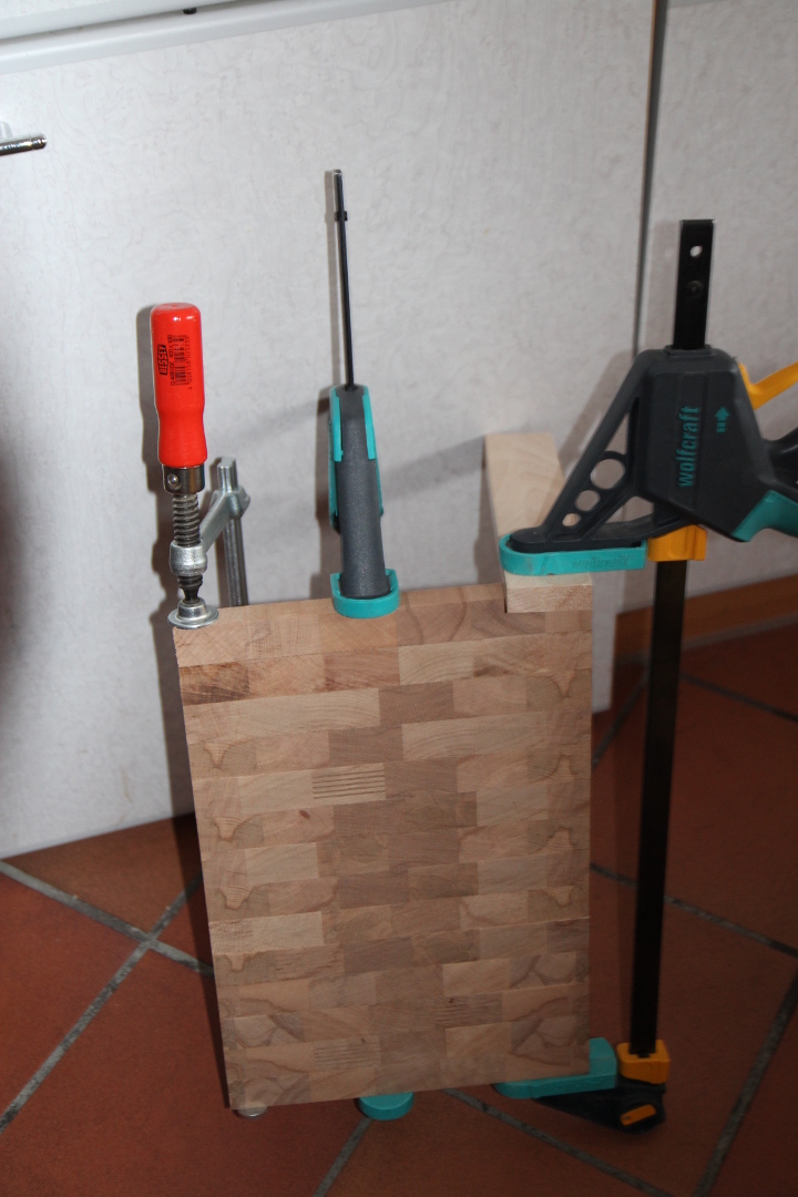
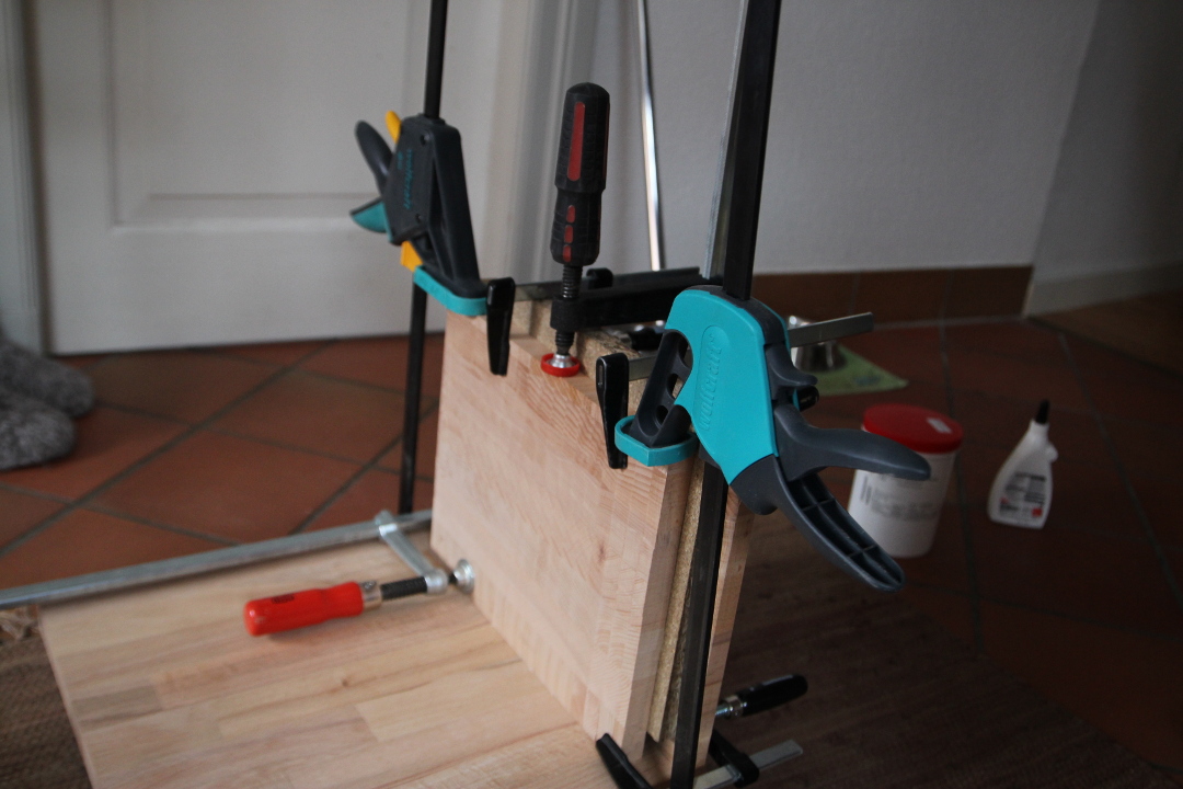
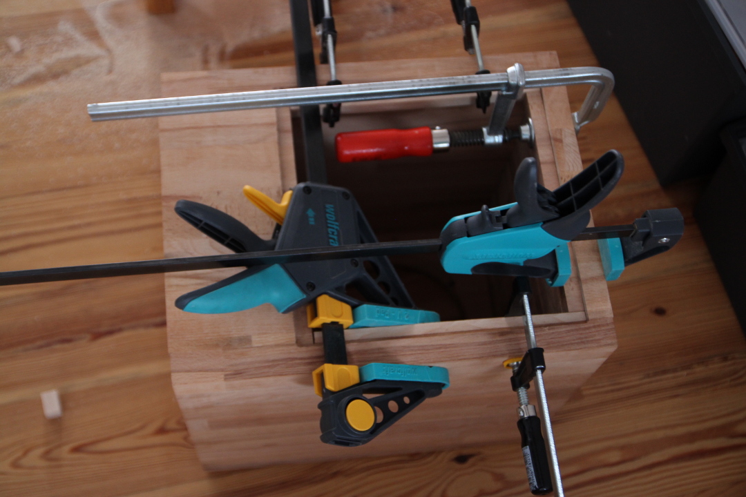
Well, I didn't have so much time, so no power planer yet. I decided to use hand planer to even the edges of the glued plates at least a little. I will do them with the power planer as well, but now they are not like plowed fields anymore.
Then I had time to do some dry fitting with clamps. Here are a couple of pictures with the sides, the front, top and bottom plates. The last two are still too long, they need to be sawed to the right length. The project is taking its shape anyhow.
I also sawed the bottom of the front plate of and glued it to the bottom plate. So the last glue bond for these plates is now drying up.
I bought a new blade for my smaller razor saw. So little money spent as well.
Money spent: €79.39
Time spent: 24 hours
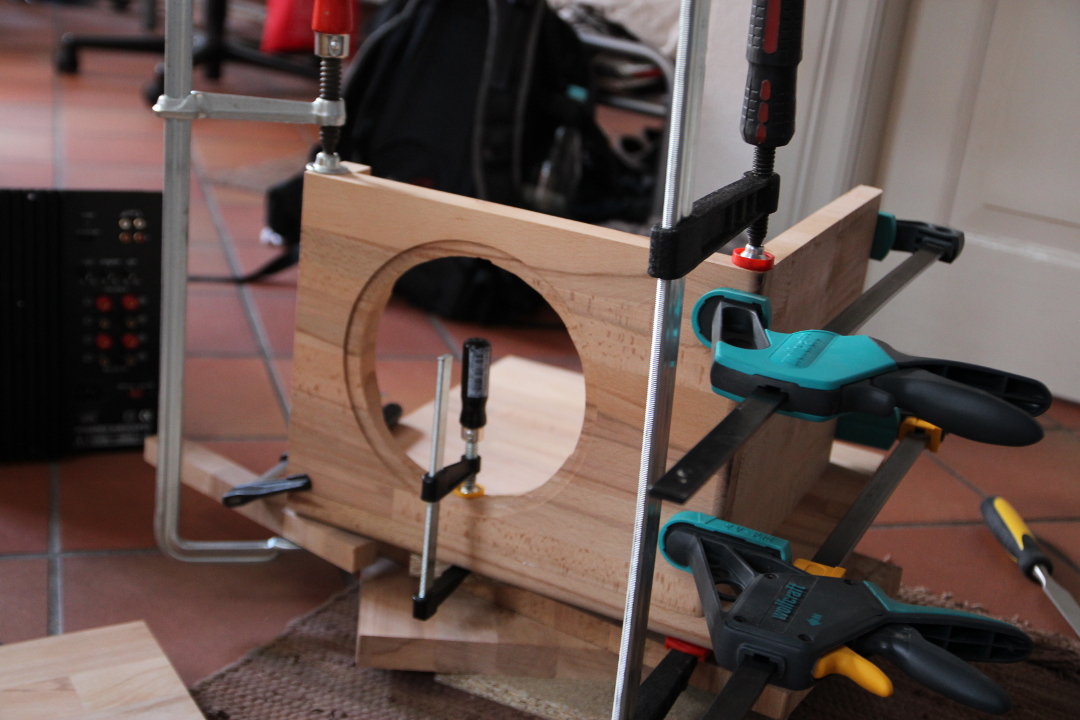
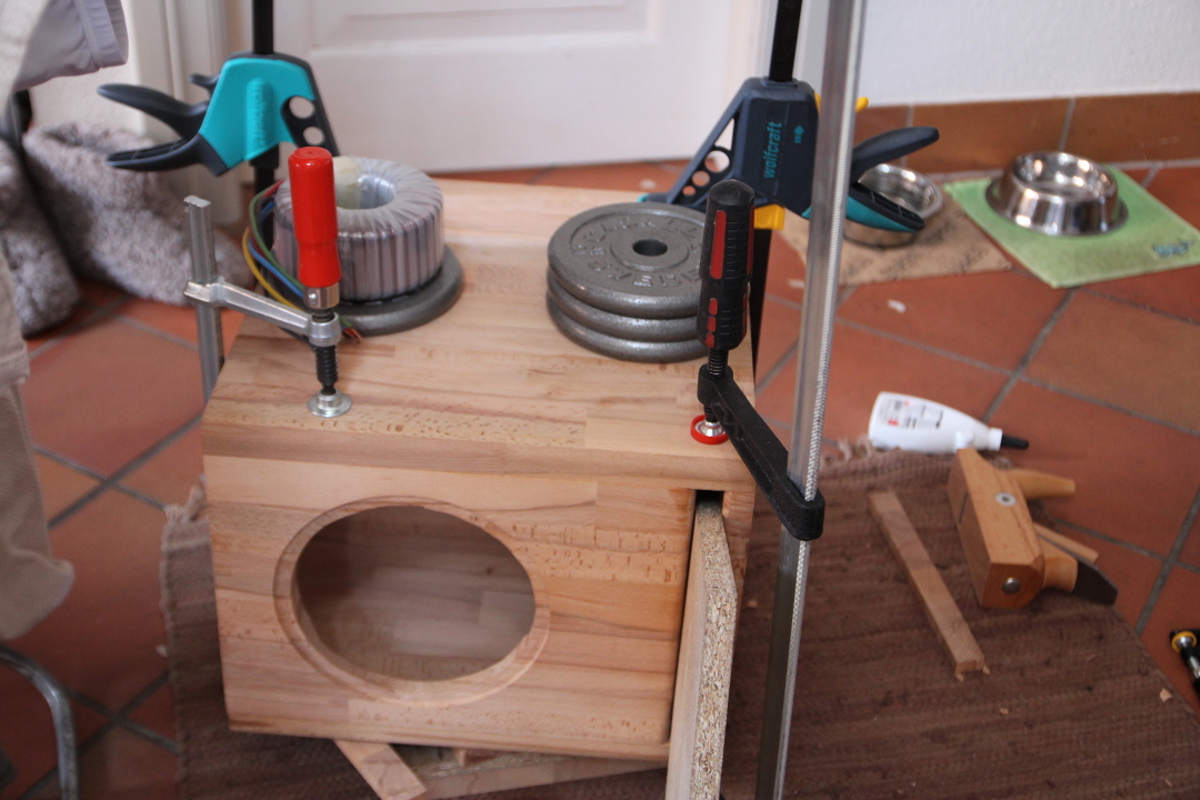
After some pondering and hand planing I decided to get the power planer after all. There are some pretty deep grooves on those bottom and top plates to take care of. Taking care of them with hand planing or sanding would take ages. As probably can be seen from this picture, the plates should be flat together.
It was taken while hand planing the middle plates to be the same width.
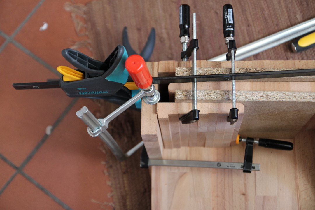
So I burned €11 to that power planer. I also bought two pieces of 19mm thick chipboard to be used as rigs for gluing the port section. They added a whopping €1.23 to my costs. After power planing I rounded the corners around and in the port with my router and a 9mm rounding bit. I also made the element opening a bit wider on the back side. After that it was time to get the glue out. So the first thing to glue was the middle part for the port. I clamped that part, one piece of the chipboard and the bottom plate together, added glue to the middle part and clamped it down.
When that had set, then the front plate.
Unfortunately the clamp on the top corner wasn't fastened tight and the small on the element opening didn't have enough pressure to keep the top part together. I had to add some more glue and clamp it again. Luckily the original glue hadn't all set before I realized this.
And after that the top plate.
As can be seen from the pictures, I work in my apartment, so I think I better add one more item to the costs: new dust bags for the vacuum cleaner. I've done quite a lot vacuuming after each building session.
Money spent: €102.61
Time spent: 36 hours
It was taken while hand planing the middle plates to be the same width.
So I burned €11 to that power planer. I also bought two pieces of 19mm thick chipboard to be used as rigs for gluing the port section. They added a whopping €1.23 to my costs. After power planing I rounded the corners around and in the port with my router and a 9mm rounding bit. I also made the element opening a bit wider on the back side. After that it was time to get the glue out. So the first thing to glue was the middle part for the port. I clamped that part, one piece of the chipboard and the bottom plate together, added glue to the middle part and clamped it down.
When that had set, then the front plate.
Unfortunately the clamp on the top corner wasn't fastened tight and the small on the element opening didn't have enough pressure to keep the top part together. I had to add some more glue and clamp it again. Luckily the original glue hadn't all set before I realized this.
And after that the top plate.
As can be seen from the pictures, I work in my apartment, so I think I better add one more item to the costs: new dust bags for the vacuum cleaner. I've done quite a lot vacuuming after each building session.
Money spent: €102.61
Time spent: 36 hours
Well, I was gone two months and I even didn't have time to post a update before leaving. So here comes one. The photos are from end of November.
First I glued the box together for those parts that were not yet glued, like the upper part of the port.
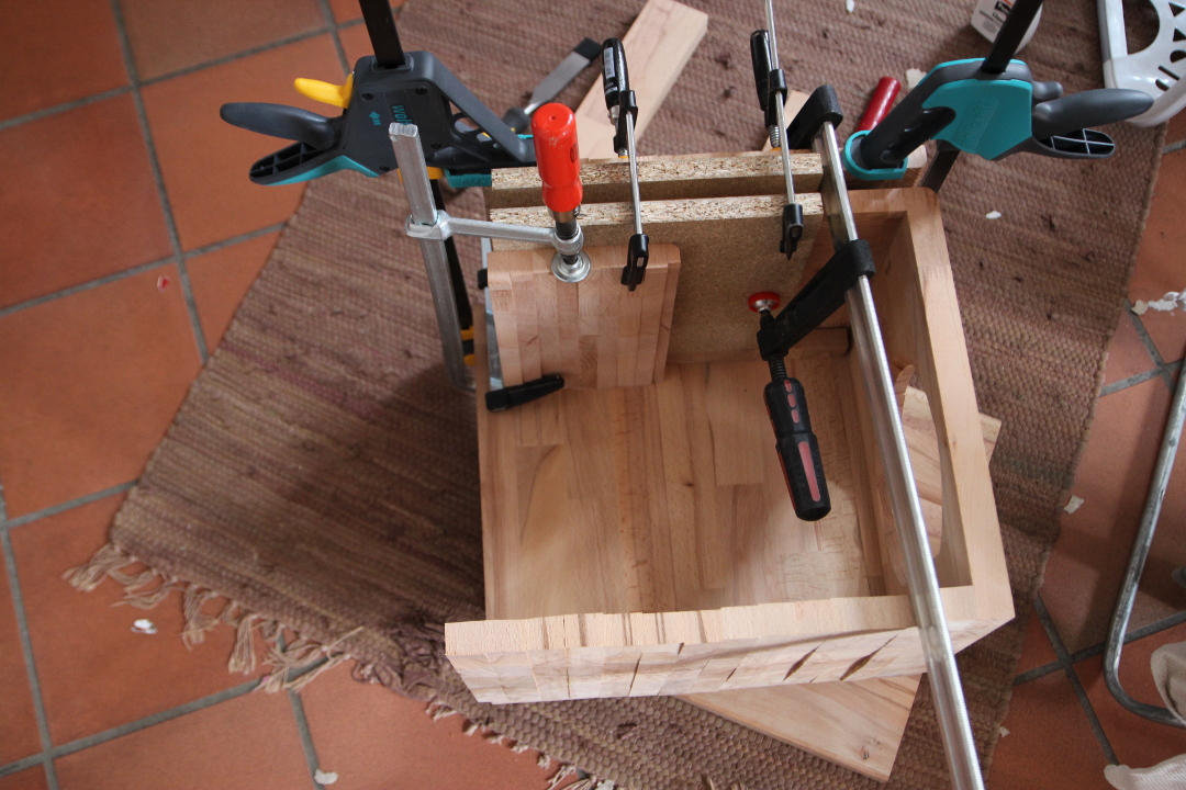
Unfortunately that was a bit too far away from the back end, so I had to do a little patch between it and the back plate.
So now the port is ready, time to check that the opening for the plate amp is big enough. It is, the plate amp fits well. I need to glue some extra strip to the top and side edges and use the router with the bottom edge.
So time to glue the other side wall to its place.
And to finish up with the amp opening by gluing the missing pieces and routing the edges.
I rented the power planer for a second time. Unfortunately the price had been altered, so I had to pay €13 for the second time. But it did help a lot with the smoothing of the bottom and top sides.
After this I bought some sanding paper for €9.20 and a kit of rubber and felt feet for €7.99. Yesterday I did finishing routing for the box edges and the first round of overall sanding. I must say that the box is starting to look pretty smooth now.
Money spent: €132.80
Time spent: 50 hours
First I glued the box together for those parts that were not yet glued, like the upper part of the port.
Unfortunately that was a bit too far away from the back end, so I had to do a little patch between it and the back plate.
So now the port is ready, time to check that the opening for the plate amp is big enough. It is, the plate amp fits well. I need to glue some extra strip to the top and side edges and use the router with the bottom edge.
So time to glue the other side wall to its place.
And to finish up with the amp opening by gluing the missing pieces and routing the edges.
I rented the power planer for a second time. Unfortunately the price had been altered, so I had to pay €13 for the second time. But it did help a lot with the smoothing of the bottom and top sides.
After this I bought some sanding paper for €9.20 and a kit of rubber and felt feet for €7.99. Yesterday I did finishing routing for the box edges and the first round of overall sanding. I must say that the box is starting to look pretty smooth now.
Money spent: €132.80
Time spent: 50 hours
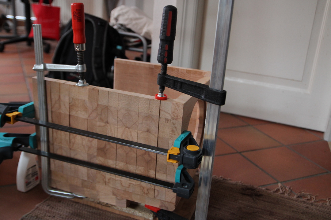
I have now done first round of sanding for the box. Here are a couple of pictures. I used flash, which brought the grain patterns more visible as the normal lighting in the room.
From the side:
From the front:
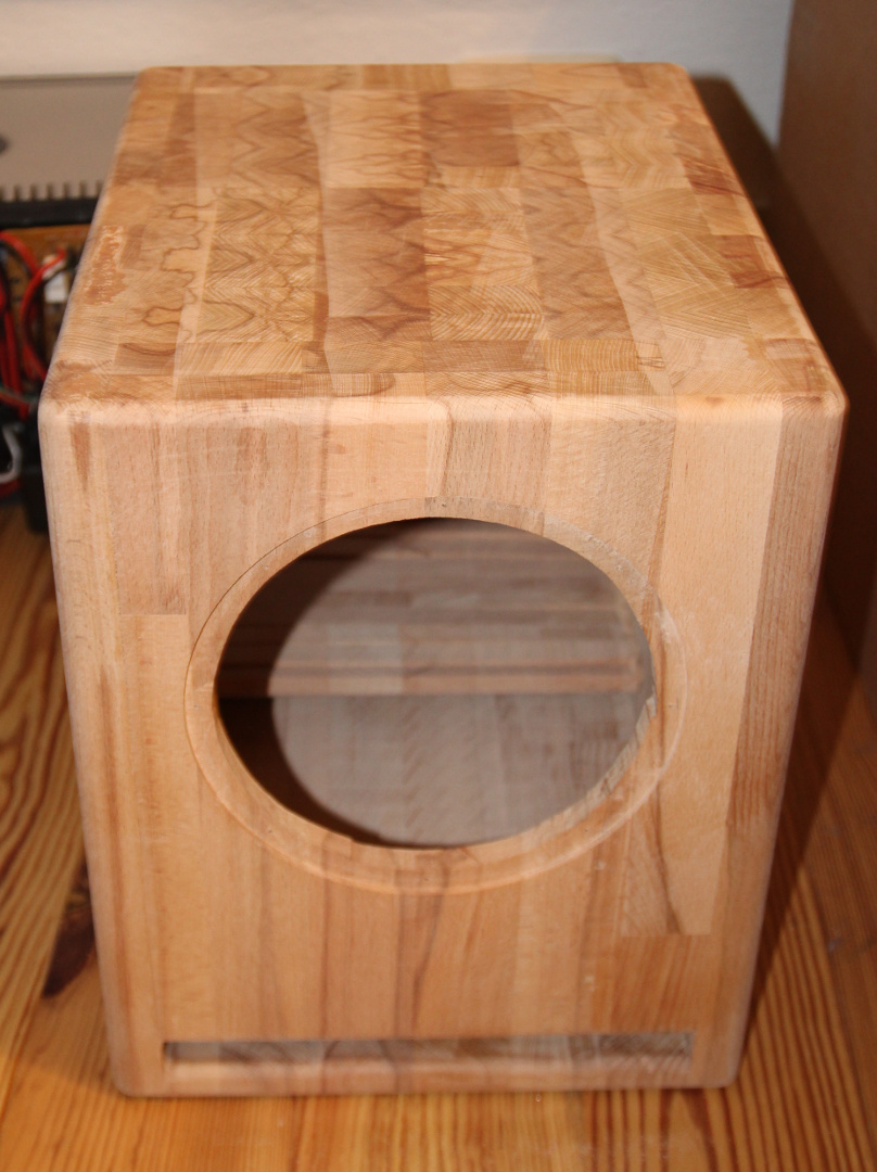
There are still some grooves on the top from the power planer, so it does need still more sanding. I think my neighbours will hate me, the power sander is pretty noisy.
From the side:
From the front:
There are still some grooves on the top from the power planer, so it does need still more sanding. I think my neighbours will hate me, the power sander is pretty noisy.
I haven't got very much time to do actual work. So what I have done is just some sanding and gluing wood for feet. I want to have some feet under the case, not letting it lie on the floor on a big surface.
But I have done some simulations during this time. Here is how WinISD predicts the driver to behave in the box I have:
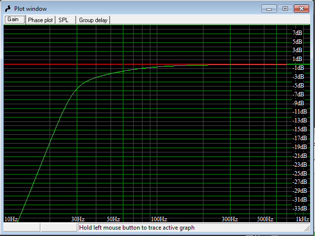
The original plan in the magazine was using an amplifier with a subsonic filter that boosts 3dB at 30 Hz. I should have something similar as well. I have downloaded a manual for the amplifier that I'm going to use and it gives nice tables how to tune the subsonic filter with a boost at different frequencies by changing resistors. Then there is an old web page in Finnish where the filters in this amplifier are reverse engineered.
So I have looked up some promising values for the resistors and have been playing with LTSpice to simulate the frequency response with those values. Next I just need to add those up with the output from WinISD to see which way to go.
Money spent: €132.80
Time spent: 57 hours
But I have done some simulations during this time. Here is how WinISD predicts the driver to behave in the box I have:
The original plan in the magazine was using an amplifier with a subsonic filter that boosts 3dB at 30 Hz. I should have something similar as well. I have downloaded a manual for the amplifier that I'm going to use and it gives nice tables how to tune the subsonic filter with a boost at different frequencies by changing resistors. Then there is an old web page in Finnish where the filters in this amplifier are reverse engineered.
So I have looked up some promising values for the resistors and have been playing with LTSpice to simulate the frequency response with those values. Next I just need to add those up with the output from WinISD to see which way to go.
Money spent: €132.80
Time spent: 57 hours
I want to have some feet under the case, not letting it lie on the floor on a big surface.
filter
A member using these feet said they work great for isolation. McMaster-Carr
Very nice so far!
I question if you really need the added factor of EQ. To double check, this is a sealed box with low Q? Room gain should be able to "EQ" the sub for you.
Also don't forget box stuffing can lower the Q. It can also reduce upper frequency reflections within the enclosure and back out the enclosure walls.
- Status
- This old topic is closed. If you want to reopen this topic, contact a moderator using the "Report Post" button.
- Home
- Loudspeakers
- Subwoofers
- Subwoofer with Postal Money