hi bart
the dimensions are inlcuding 18mm wood thickness,and the sims asumes 2 bracings 12mm over the full lenght of the horn.
from front of the speaker baffle to the back is 22.11 cm.
you could make a spacer/ring to move the driver forward if needed.
all dimensions can easely be changed to the current dimensions.
what freq range are you aiming at?
I aim as low as possible, the top end would be less important.
I've got something else to compensate for that.
The second driver I have would be placed in a box between L&R, tuned to a higher frequency (about 27hz maybe) mostly for music.
The sub talked about in this thread would only come in for movies and not be used otherwise.
So it really can be a dedicated sub in the pure sense of the word.
These two would be powered by a NU6000DSP
The sub in this thread would not use a HPF, the other one would of course.
So, if at all possible, I would like to build a sub that go's very low and doesn't need a HPF.
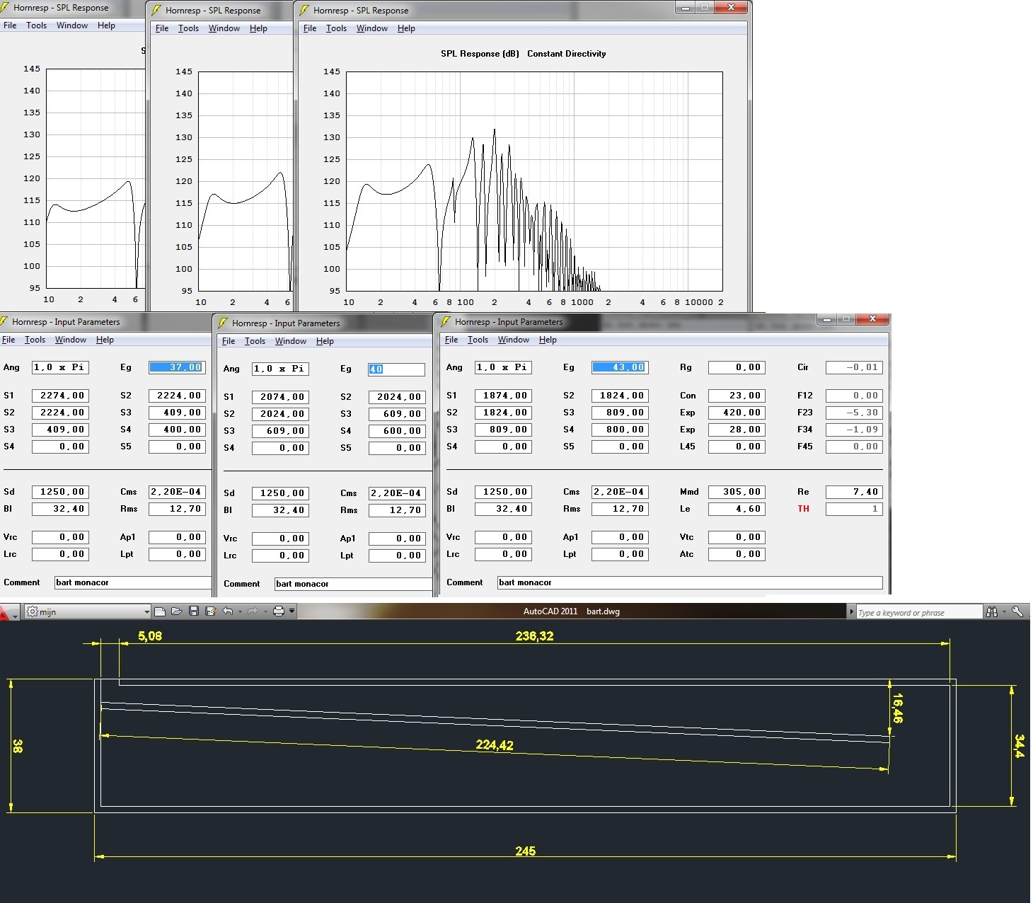
I tried to enlarge the floorspace with the numbers that had to be used in the first place and just multiplied epa's numbers with the difference in surface, being about 1.3
This is the graph that came out.
Maybe if the compression ratio would be different it could even get better but not much time right now.
I'll see if I can come up with something sensible later.
Thoughts?
This is the graph that came out.
Maybe if the compression ratio would be different it could even get better but not much time right now.
I'll see if I can come up with something sensible later.
Thoughts?
Attachments
So, if at all possible, I would like to build a sub that go's very low and doesn't need a HPF.
Infra-bass low & loud of course means high efficiency & high power handling, so see no way to get both in a reasonable size regardless of whether or not it has a HPF unless it's a spare large closet or room, basement or attic sub system.
GM
Thanks! ")
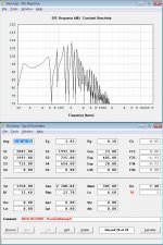
Which one of the three simulations is used to draw the CAD drawing?
I'm wondering if I can sim this with two drivers or is hornresp limited to one driver TH's?
And how do I change the placement of the driver? Maybe there's a workaround to use two drivers, by changing the driver parameters accordingly.
Do you think this is correct? I hope I start simulating useful stuff from here on. 
Does this ask for a HPF or can it be used without? I mean, is there any content below 12hz and at full volume, in movies?
Hmmm, what would Xmech be?
Thanks a lot, everybody, for the work you've put in so far. Especially epa.
Maybe it's best to hold off the CAD drawings for now, until there's a winner amongst these simulations.
Attachments
its the one that go's lowest.
you can put 2 drivers in np,in the main screen go to>tools> driver arangement.there you can set the number of drivers.
parameters are calculated automagisch.
if you want 2 drivers you have to place one a bit higher to fit in the cab.
ah 3 minutes late....
with 2 drivers looks even better
serious output ,you think you need 122 db?
Last edited:
Hi Bart,
Looking at epa's simulations in Post #25, the sum of S2 and S3 is 2633, you seem to have found additional cross-sectional area in Post #28: S2 + S3 = 2707. Your S4 is only 500, I would suggest not to go below Sd/3 (2x1250/3=833.3). You have the drivers connected in series. It may not make a difference in a HT application, but the example from Post #28 needs a 10Hz LR4 HP with the given Eg.
Regards,
HP?
Hi Bart,
In the home you will probably not reach Xmax, but why risk it? I like the HP (low cut) filter.
Now, in a lot of systems you don't have signal response down to DC anyway, so, if the system already attenuates the low end of the signal, you may not need a dedicated HP.
Regards,
Hi Bart,
In the home you will probably not reach Xmax, but why risk it? I like the HP (low cut) filter.
Now, in a lot of systems you don't have signal response down to DC anyway, so, if the system already attenuates the low end of the signal, you may not need a dedicated HP.
Regards,
Yes it looks nice and I don't think in real live usage, I'll need the HPF. I'll just set the limiter and be done with.
I was thinking along the line of building two subs, half the width and each enclosure one driver.
Start with one and hear how that go's. then I still have the choice of leaving it like that, because, let's be honest, a TH like that will shake the house quite a bit with only one driver. (it already does in a BR!)
Besides, I have the opportunity to place a second one somewhere else (room nodes)
Or use the second driver between the L&R channel, tuned a bit higher. These TH will only reach up to 60hz... Still pondering...
At this very moment I'm mailing with mr. Kirchner ([ATB PC PRO]Kirchner elektronik - Onlineshop) about the T&S measurement of these drivers.
I'm about to send him a screenshot of the problem and hope it will get resolved. (updates will be posted on that)
I was thinking along the line of building two subs, half the width and each enclosure one driver.
Start with one and hear how that go's. then I still have the choice of leaving it like that, because, let's be honest, a TH like that will shake the house quite a bit with only one driver. (it already does in a BR!
)Besides, I have the opportunity to place a second one somewhere else (room nodes)
Or use the second driver between the L&R channel, tuned a bit higher. These TH will only reach up to 60hz... Still pondering...
At this very moment I'm mailing with mr. Kirchner ([ATB PC PRO]Kirchner elektronik - Onlineshop) about the T&S measurement of these drivers.
I'm about to send him a screenshot of the problem and hope it will get resolved. (updates will be posted on that)
2 TH's
Hi there B: Agree, your HR design and graphs for a single TH using 2 Series drivers look exceptional. However, recommend that you redo the HR simulation for a single driver TH enclosure, the sim' may be different (much different is possible) when you cut the width in half (reduce the areas). I've have had the opposite happen, single TH not acceptable and a 2 series driver TH look good. ...regards, Michael
Yes it looks nice...
I was thinking along the line of building two subs, half the width and each enclosure one driver.Start with one and hear how that go's. then I still have the choice of leaving it like that....
Hi there B: Agree, your HR design and graphs for a single TH using 2 Series drivers look exceptional. However, recommend that you redo the HR simulation for a single driver TH enclosure, the sim' may be different (much different is possible) when you cut the width in half (reduce the areas). I've have had the opposite happen, single TH not acceptable and a 2 series driver TH look good. ...regards, Michael
j.michael droke,
Both graphs should be the same, whether they are in series, parallel or only one driver at half the surface. Except for the SPL of course.
It's very time consuming for me to use all sorts of programs and I'm struggling with my second driver because I want to use measured specs.
Since this driver is not broken in yet, I suspect that is the reason my measurements are so far off.
I remember when my first BR with this driver didn't sound good at all, until after about 5 hours, then it started to get better and better. I think it's stabilized somewhat now.
I'll try to get a transformer hooked up this afternoon that can drive the sub in free air without smoking either of them.
I was thinking ±24V. This would be 72W at 8Ω
Thanks epa, but not so fast! lol. This is still in the thinking jar.
At this very moment, the 18" woofer is getting 43.8V @ 2.75A
That's ±120.5W and results in a resistance of about 16Ω@50hz
Previously I've put half the Voltage on it and the cone movement P-P was about 6mm
Now it's about 12mm and the air, deep in the magnet vent hole, is about 34°C.
side-note: the transformer pulls 127W from the socket. This means it only looses 6.5W on the way to the woofer. 5.4% loss. This gives me confidence that the transformer won't blow up anytime soon. (it's not overloaded)
I did put it on a cooling fin, with some dishwasher liquid between the two, for heat conduction. Fin is at ±34°C too.
ambient temp is 23°C
The woofer does make a humming sound of course and a bit of vent hole wind noise, but I don't want to leave the house for the annoying hum and risk a fire.
Another important thing... While trying to measure T&S parameters I realized that my method has a flaw. The woofer is just sitting loosely so it can rock back and forth much more then when it would be mounted in a box. I think this is the reason the parameters don't resemble the factory specs.
At this moment I don't have any good way of mounting the driver tight or don't know how to weigh down the basket in a good and heavy way to reduce the woofer from moving too much. Any tips?
[URL=http://tinypic.com/r/vebsoy/5]Here's a HD-video ☺[/URL]
↑click↑
Attachments
Last edited:
- Status
- This old topic is closed. If you want to reopen this topic, contact a moderator using the "Report Post" button.
- Home
- Loudspeakers
- Subwoofers
- 18" in horn for HT