Low distortion, DSP based high gain servo controlled subwoofer controller.
Hi,
This is a work in progress based on an initial prototype (REV:A) and nothing is set in concrete yet so I’d thought I’d share some of the preliminary results I have achieved thus far which look very promising.
I was going to put this in the subwoofer section except the main goal of this device is for accurate bass reproduction of music using a servo controlled woofer in a sealed box, open or infinite (large wall or floor mount) baffle systems. Typically it would be used as part of a multi-way passive or fully active speaker system or a stand-alone subwoofer system used to complement an existing full range speaker that cannot cover the bottom octaves. It has a fully programmable active crossover feature that can be used as a two-way stereo system with two dedicated bass servo channels. Alternatively it can be set up as a mono 3 or 4 way active system including one dedicated bass servo.
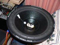
The board is designed to interface directly to a highly linear and low noise industrial grade accelerometer, namely a Measurement Specialties ACH-01-03 accelerometer. A novel mounting method directly couples the accelerometer to the voice coil which minimizes base strain and thermal coupling to the accelerometer. This accelerometer features an integral shielded flexible lead and a +/- 150g capability with a 30KHz mechanical resonance. This is the same accelerometer used in a $50,000 reference speaker system for the same type of application. It can be purchased from a number of sources including Digikey and Mouser for as little as $20.
A simple design procedure using fully automated measurement to characterize the speaker and box simplifies the entire design process without requiring any specialized or expensive equipment. No PhD required in electronics or electro-acoustics") A servo woofer design can be implemented and operating in less than 30 minutes !!
A servo woofer design can be implemented and operating in less than 30 minutes !!
Initial testing and measurements are promising with a maximum of 43 dB reduction in motor distortion achievable. Most commercial systems only provide between 6-12 dB reduction in THD.
Any questions and suggestions are welcome and any of the specifications are subject to change. I hope to make this thread a blog on my progress with this project so any feedback is welcome.
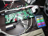
1st image - DSP servo controller,
2nd image - Test loudspeaker with accelerometer mounted to the voice coil,
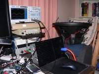
3rd image - The whole setup,
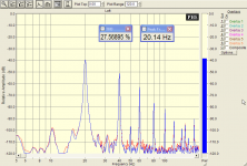
4th image - Distortion results at 20Hz before feedback,
5th image - Distortion results at 20Hz after 30 dB feedback applied,
Regards
David
Hi,
This is a work in progress based on an initial prototype (REV:A) and nothing is set in concrete yet so I’d thought I’d share some of the preliminary results I have achieved thus far which look very promising.
I was going to put this in the subwoofer section except the main goal of this device is for accurate bass reproduction of music using a servo controlled woofer in a sealed box, open or infinite (large wall or floor mount) baffle systems. Typically it would be used as part of a multi-way passive or fully active speaker system or a stand-alone subwoofer system used to complement an existing full range speaker that cannot cover the bottom octaves. It has a fully programmable active crossover feature that can be used as a two-way stereo system with two dedicated bass servo channels. Alternatively it can be set up as a mono 3 or 4 way active system including one dedicated bass servo.
The board is designed to interface directly to a highly linear and low noise industrial grade accelerometer, namely a Measurement Specialties ACH-01-03 accelerometer. A novel mounting method directly couples the accelerometer to the voice coil which minimizes base strain and thermal coupling to the accelerometer. This accelerometer features an integral shielded flexible lead and a +/- 150g capability with a 30KHz mechanical resonance. This is the same accelerometer used in a $50,000 reference speaker system for the same type of application. It can be purchased from a number of sources including Digikey and Mouser for as little as $20.
A simple design procedure using fully automated measurement to characterize the speaker and box simplifies the entire design process without requiring any specialized or expensive equipment. No PhD required in electronics or electro-acoustics
A servo woofer design can be implemented and operating in less than 30 minutes !!Initial testing and measurements are promising with a maximum of 43 dB reduction in motor distortion achievable. Most commercial systems only provide between 6-12 dB reduction in THD.
Any questions and suggestions are welcome and any of the specifications are subject to change. I hope to make this thread a blog on my progress with this project so any feedback is welcome.
1st image - DSP servo controller,
2nd image - Test loudspeaker with accelerometer mounted to the voice coil,
3rd image - The whole setup,
4th image - Distortion results at 20Hz before feedback,
5th image - Distortion results at 20Hz after 30 dB feedback applied,
Regards
David
Attachments
Last edited:
I have some tests that I did at 15Hz that I will post tomorrow. Because this speaker is a car speaker its linearity is very bad below its resonant frequency which is about 30Hz. It has a lot of motor and suspension non linearity and probably a very limited X-max of 10mm or less. There is no flux shorting ring so it also has a lot of high frequency distortion as well. The drive current to produce all of the distortion was not very much which makes it ok for car use because only SPL matters in that application
However for the purposes of comparison of before and after it is the ideal test candidate. Also it can handle lots of power so mishaps are not going to kill it. Quite often I have driven the Power Physics 1000 watt amp into clipping when I was developing the DSP code
regards
David
However for the purposes of comparison of before and after it is the ideal test candidate. Also it can handle lots of power so mishaps are not going to kill it. Quite often I have driven the Power Physics 1000 watt amp into clipping when I was developing the DSP code
regards
David
Cool! It does look like the ideal test driver for what you are doing. Looking forward to seeing more results. Also very interested to see what your DSP will do once the speaker is mounted in an enclosure. Running before and after DSP sweeps with something like ARTA-Steps or HOLMImpulse would show how well the DSP feedback handles any problems coming from the box itself.
What the immediate goal? Will you be telling us enough about the system that we can build one ourselves?
What the immediate goal? Will you be telling us enough about the system that we can build one ourselves?
Yes it's aimed at diyers or OEMs etc who want to build high quality servo controlled (sub)woofers without requiring a PhD in electronics or electro-acoustics I have done all of the ground work for them and encapsulated it in the dsp hardware/software as well as providing a user friendly windows app that communicates with the board via a USB connector
Whether the speaker is mounted in a sealed enclosure or open baffle etc ultimately the whole package is designed to quickly measure, analyse and commission a complete servo controlled woofer system from start to finish without requiring any specialized or expensive test equipment. Also the design is not tied to a particular loudspeaker or amplifier vendor although it would be unwise to use a cheap speaker with a high resonant plastic cone etc. Whilst the servo can fix up motor problems it can't perform miracles on a poorly designed speaker with bad diaphragm vibration modes and resonances
However there are no need for special drivers with sensing coils that can only be purchased from the one source. Hopefully some driver manufacturers may jump on board and build the accelerometer into their speaker so they can add more value to their products since you can now buy these accelerometers off the shelf for less than $20 in one off quantities which is a bargain compared to what you would pay for the equivalent device 10 years ago. If not the diyer can still mount the accelerometer themselves just I have done on the prototype.
It's still early days yet and the dsp code is an ongoing concern but its all starting to converge to a final end point hopefully
I will post some more measurements tomorrow as I am not at my other computer at the moment.
P.S. The same accelerometer is used in a $50,000 reference speaker system for the same type of application. Hopefully my system gives much better performance
regards
David
I have done all of the ground work for them and encapsulated it in the dsp hardware/software as well as providing a user friendly windows app that communicates with the board via a USB connector Whether the speaker is mounted in a sealed enclosure or open baffle etc ultimately the whole package is designed to quickly measure, analyse and commission a complete servo controlled woofer system from start to finish without requiring any specialized or expensive test equipment. Also the design is not tied to a particular loudspeaker or amplifier vendor although it would be unwise to use a cheap speaker with a high resonant plastic cone etc. Whilst the servo can fix up motor problems it can't perform miracles on a poorly designed speaker with bad diaphragm vibration modes and resonances
However there are no need for special drivers with sensing coils that can only be purchased from the one source. Hopefully some driver manufacturers may jump on board and build the accelerometer into their speaker so they can add more value to their products since you can now buy these accelerometers off the shelf for less than $20 in one off quantities which is a bargain compared to what you would pay for the equivalent device 10 years ago. If not the diyer can still mount the accelerometer themselves just I have done on the prototype.
It's still early days yet and the dsp code is an ongoing concern but its all starting to converge to a final end point hopefully
I will post some more measurements tomorrow as I am not at my other computer at the moment.
P.S. The same accelerometer is used in a $50,000 reference speaker system for the same type of application. Hopefully my system gives much better performance
regards
David
Interesing stuff, nice job!
What is theoretical upper frequency the device can "fix" based on accellerometer and samplerate/converter latency?
cheers,
Kees
Hello Kees
I run the ADC's and DAC's at the fastest rate of 192 KHz which minimizes total group delay to 7.5/fs or about 37.5 uS. Then add to that delay through the dsp processing and analog sections and you can expect about 4 degrees phase shift at 100Hz. Believe it or not most of the phase shift comes from the driver because above the piston range of the driver the diaphragm acts as a transmission line with many different vibration modes and exhibits a very complex impedance depending on how it is constructed and how it is terminated at the surround. This is why one vendor of servo systems uses drivers with rigid metal cones. I have an 8 inch driver with aluminium cone and I can confirm it performs much better than paper.
For stability reasons I purposely limit the maximum open loop gain bandwidth to 120Hz. Above this frequency, current feedback reduces high frequency distortion due to inductance modulation. Limiting the open loop gain bandwidth means I don't need to use drivers with special construction because the vibration modes will fall outside the bandwidth of the servo amplifier
I will post some more measurements.
regards
David
Last edited:
Thanks David.
FYI, that accelerometer is $38 at Mouser here in the USA. Not bad, and it may be a useful tool for all sorts of other things, like panel resonances.
A few weeks ago Digikey had them for $20 whilst Mouser was $40 but now they have gone back up again.
Bummer I should have bought a heap of them regards
david
Impressive indeed.
Does this enable speaker to make nice 20Hz square wave?
As long as the speaker uses a rigid diaphragm it is quite possible to accurately produce a 20Hz square wave
regards
david
Hi,
4th image - Distortion results at 20Hz before feedback,
5th image - Distortion results at 20Hz after 30 dB feedback applied,
Hi David,
The level of fundamental (20Hz) in 5th image is about 2dB lower than in 4th image (before feedback).
Are you able to provide feedback results for fundamental of exactly the same level as in the 4th image?.
Best Regards,
Bohdan
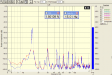
Speaker/Accelerometer 15 Hz Single Tone Test
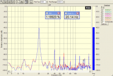
This test shows a worst case scenario which emphasizes suspension and motor distortion and the effectiveness of feedback to clean it up This speaker produces loads of distortion below it's resonant frequency. The lower the frequency the more dominant the distortion mechanisms. I would not recommend it for HiFi use
1st Image - Distortion Spectrum with Voltage Drive and no feedback
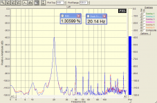
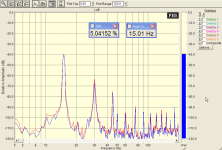
2nd Image - Distortion Spectrum with Servo and 30 dB loop gain
3rd Image - Distortion Spectrum with Servo and 30 dB loop gain + boost
4th Image - Oscilloscope shot with Voltage Drive and no feedback*
5th Image - Oscilloscope shot with Servo and 30 dB loop gain*
* Oscilloscope top yellow waveform is the accelerometer output
* Oscilloscope bottom blue waveform is the voice coil current
This test shows a worst case scenario which emphasizes suspension and motor distortion and the effectiveness of feedback to clean it up
This speaker produces loads of distortion below it's resonant frequency. The lower the frequency the more dominant the distortion mechanisms. I would not recommend it for HiFi use 1st Image - Distortion Spectrum with Voltage Drive and no feedback
2nd Image - Distortion Spectrum with Servo and 30 dB loop gain
3rd Image - Distortion Spectrum with Servo and 30 dB loop gain + boost
4th Image - Oscilloscope shot with Voltage Drive and no feedback*
5th Image - Oscilloscope shot with Servo and 30 dB loop gain*
* Oscilloscope top yellow waveform is the accelerometer output
* Oscilloscope bottom blue waveform is the voice coil current
Attachments

Last edited:
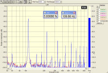
Speaker/Accelerometer 110 Hz Single Tone Test
The following measurements compare the effectiveness of current drive alone in reducing high frequency distortion. About a 14 dB reduction in distortion can be achieved with current drive depending on the drive level. Unfortunately current drive is worse than voltage drive at frequencies below the resonant frequency which is where the global feedback is effective
1st image - Distortion Spectrum with Voltage Drive and NO global feedback
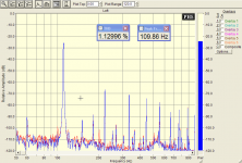
2nd image - Distortion Spectrum with Current Drive and NO global feedback
The following measurements compare the effectiveness of current drive alone in reducing high frequency distortion. About a 14 dB reduction in distortion can be achieved with current drive depending on the drive level. Unfortunately current drive is worse than voltage drive at frequencies below the resonant frequency which is where the global feedback is effective
1st image - Distortion Spectrum with Voltage Drive and NO global feedback
2nd image - Distortion Spectrum with Current Drive and NO global feedback
Attachments
Last edited:
Impressive!
Will for sure be interested in buying one of these when you finish!
5 years ago I made an analogue servobass system with the same accelerometer and was able to drop THD from 26% to 5% on my Peerless XLS 10" woofer. This was at full X-MAX of 12mm and at 23Hz. I ran into problems with the soft dust-cap that created resonances at about 500Hz. I had to mount the accelerometer directly over the voice coil which again created wrong balance in the cone. The accelerometer weighs 4 grams and when the g-forces reached about 70g the coil crashed into the magnet
Anyway, it seems your system has much better potential. Have you looked into mounting one of these super-small chip accel availiable?
http://www.analog.com/static/imported-files/data_sheets/ADXL193.pdf
Can you show me the open loop in a bode plot? It looks nice, but the DSP*Wooferdynamics is what is the really interesting part.
Ideally a separate DSP implementation and a separate Woofer-model.
Next to that, have you measured the latency of the DSP from analog in to analog out?
Ideally a separate DSP implementation and a separate Woofer-model.
Next to that, have you measured the latency of the DSP from analog in to analog out?
Can you show me the open loop in a bode plot? It looks nice, but the DSP*Wooferdynamics is what is the really interesting part.
Ideally a separate DSP implementation and a separate Woofer-model.
Next to that, have you measured the latency of the DSP from analog in to analog out?
A lot of it is proprietary so can't share too many details, suffice to say that I use a novel approach that allows me to define the frequency response or speaker alignment independent of the servo amplifier response. Most servo designs have to build the closed loop frequency response around the servo amplifier and the requirements of stability. Currently I use a simple 2nd order high pass shaping filter and I can select the cutoff frequency and Q independent of the servo amplifier bandwidth and gain. You could use other shaping filters such as 3rd or 4th order Butterworth or Bessel etc which would give additional subsonic filtering but poorer group delay and transient response.
Regarding latency the total group delay or transit time of the adc and dac chain is 7.5/fs @192KHz. This is about 37.5uS. But add to that the extra dsp processing and delay in the analog circuitry gives about a net 4 degree phase shift at 100Hz. To put that into perspective the phase shift of the compensation of the servo amplifier swamps the group delay by a large margin whilst still maintaining unconditional stability
regards
david
Impressive!
Will for sure be interested in buying one of these when you finish!
5 years ago I made an analogue servobass system with the same accelerometer and was able to drop THD from 26% to 5% on my Peerless XLS 10" woofer. This was at full X-MAX of 12mm and at 23Hz. I ran into problems with the soft dust-cap that created resonances at about 500Hz. I had to mount the accelerometer directly over the voice coil which again created wrong balance in the cone. The accelerometer weighs 4 grams and when the g-forces reached about 70g the coil crashed into the magnet
Anyway, it seems your system has much better potential. Have you looked into mounting one of these super-small chip accel availiable?
http://www.analog.com/static/imported-files/data_sheets/ADXL193.pdf
Yes I bought some NOS ADXL250's some time ago from ebay but didn't use them in the end. The problem with some of the mems devices is they have much more noise compared to the piezo devices. The ACH-01-03 is a very low noise device which makes it ideal for this type of app.
There are even better Measurement Specialities devices I have looked at such as the 805 and 805M1 but they are more expensive and need to be mounted on a pcb etc and don't have an integral flexible coax lead.
Mounting of the accelerometer is crticial. As soon as you mount it on a dust cap you create a mechanical resonance depending on the weight of the accelerometer and the mechanical compliance of the dust cap. This resonance can vary from a few hundred Hz to the KHz region and makes this type of mounting totally futile in most cases. The end result is to make the system unstable and turn it into an oscillator.
I have an 8 inch aluminum coned woofer and I mounted the accelerometer onto the aluminum dustcap using bluetack of all things. It works quite well but exhibits a sharp peak resonance of 15 dB at 1.3KHz. Without filtering the system will oscillate at about 1.3KHz. But I have built in a user defined fully customizable anti-modal filter which can essentially null out this resonance and eliminate any instability
At the end of the day the accelerometer should be tightly coupled to the voice coil but even then you have to deal with modal resonances in the speaker cone. Again the anti-modal filter built into the dsp software comes to the rescue regards
david
- Status
- This old topic is closed. If you want to reopen this topic, contact a moderator using the "Report Post" button.
- Home
- Loudspeakers
- Subwoofers
- Low distortion, DSP based high gain servo controlled woofer controller.