The impedance curve (which, I hope everybody now understands, reflects the motion of the cone) is the only reliable way (short of an anechoic chamber) to really know how your BR construction is working.
As Ron E indicated, the impedance curve reflects cone VELOCITY, not cone DISPLACEMENT, the latter of which is significantly more important in BR design (in fact, this should have been made pretty clear to you by Oscar's responses in this thread). NO-ONE I know designs BR systems with "cone velocity" or "acheiving equal impedance humps" in mind - the focus usually is on achieving a response curve AND power handling within the passband, and only AFTER the build is done, they use the impedance response curve to determine (1) if they achieved target Fb and (2) there aren't significant losses in the as-built system (which will be reflected in the impedance curve).
Maybe the design process you suggested was "traditional" back in the 1950's, I don't know. Wasn't born then. Don't care anyway. However it certainly isn't "traditional" now IMO, and to characterize it as such is ludicrous.
Anyway, be thankful Ron gave you an "out" by relating the impedance curve to cone velocity. I am pretty sure you were actually referring to DISPLACEMENT, particularly with your comment in post #25 where you actually referred to displacement when you pontificated that "Below, the cone is also moving because it has nothing additional to the suspension to hold it back. So it moves more. And the impedance curve, contrary to your ardent assertion, also is elevated in a related way.", when it's very clear that the impedance curve is DECREASING after the lower peak, and EXCURSION is INCREASING (and significantly so) at the same point, basically disproving the same point you were trying to make.
And, as for your comment about modelling sealed enclosures, I'll give it the due attention it deserves
") .
.Ben,The impedance curve (which, I hope everybody now understands, reflects the motion of the cone) is the only reliable way (short of an anechoic chamber) to really know how your BR construction is working.
Ben
*as far as I'm concerned, there's no model that is especially useful for building sealed enclosures. Bigger is better and you choose the trade-offs.
Outdoor measurements using a dual FFT like Smaart(the program I use) are far more accurate than anechoic chambers for bass, as "anechoic chambers", unless huge (several wavelengths long), and filled with literally tons of absorbent material, are not anechoic at low frequencies.
Hornresp will model sealed enclosures as accurately as it models BR, TH, FLH, and various combinations of the above, but actual measurements are important to see if the cabinet performs as simulated.
When using amps that can adequately deal with the DC resistance of a cabinet (most have an impedance minima very close to DCR), the impedance curve has little consequence.
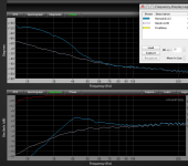
Phase and frequency response as shown below in the outdoor measurements of a BR and sealed cabinet (the same enclosure with ports closed off) inform one as to what is needed for alignment to top cabinets at the crossover point and basic EQ, final EQ is room and placement oriented.
The same test gear can be used in room for verifying response in various room locations.
Art
Attachments
- Status
- This old topic is closed. If you want to reopen this topic, contact a moderator using the "Report Post" button.