All true, and covered in whitepaper #2. I was simplifying things to help clarify the thought process on why a current source might be a better solution than a voltage source for this application…perhaps I should have stated that. As I mentioned, other than distortion reduction at higher frequencies where excursion is low and MFB loop gain is low I hadn't found particular benefit to current source drive.Unfortunately, nonlinearities at the edges of the magnetic field and voice coil, as well as nonlinearities in the spider and surround, ensure that the force actually applied to the speaker cone is not proportional to the current when voice coil excursions are large... the claim that force is proportional to current fails to hold true under exactly the conditions where MFB is most useful!
Many thanks to the clarifications of bolserst and Gnobuddy.
Just a comment, the issue of 30dB feedback may look feasible in a lab but not survive in a house. I used a near-DC-coupled amp for most of my experience but the loop weirdness inheres in the speaker, so a more perfect amp helps only a bit.
Not clear to me when we are talking current versus voltage behaviour with MFB or that it matters in design particularly when using an accelerometer which doesn't necissarily model the back EMF of the voice-coil even if it does mimic the motion of the dust cap.
With a bridge or current sensor we are obviously trafficking in voice-coil motion and MFB provides a correction output which makes the amp display negative output impedance. I don't know enough to say if that is current-amp behaviour or voltage or that it matters since the amp firmware is the same.
(Maybe it is just aesthetics, but it seems more elegant to have a feedback loop with a single transducer in it than two (driver and accelerometer.))
B.
Last edited:
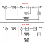
As mentioned in post#779, negative current feedback is used for operating an amplifier as a current source. This results in very large positive output impedance. Again, this is completely different from the use of positive current feedback to generate small amounts of negative output impedance to attempt cancellation of the VC resistance and improve damping. The former achieves best results with as much feedback loop gain as possible. The latter needs a very specific amount of feedback loop gain to achieve cancellation.…With a bridge or current sensor we are obviously trafficking in voice-coil motion and MFB provides a correction output which makes the amp display negative output impedance.
In either case (voltage source amplifier or current source amplifier) you are operating with an inner and an outer feedback loop. In the voltage source case, the inner feedback loop is forcing the voltage applied to the woofer to follow or be proportional to the amplifier input voltage. In the current source case, the inner feedback loop is forcing the current driven thru the woofer to follow or be proportional to the amplifier input voltage.(Maybe it is just aesthetics, but it seems more elegant to have a feedback loop with a single transducer in it than two (driver and accelerometer.))
The differences between the two drive methods will mainly show up at frequencies where the outer loop gain has fallen below 1. In these frequency ranges, the current source method has the potential to reduce inductance modulation related woofer distortion.
Attachments
In response to Bolserst's post #479. First, thanks for these good sims.The 12” AR woofer had a moving mass of roughly 100g…so not exceedingly low. The only one I got to measure had Fs = 16Hz and suspension compliance equivalent to about 270ltr (9.5ft^3). There are a few 12” subwoofer drivers out there with similar parameters that will give similar response in similar enclosure sizes. For example, the ScanSpeak 30W/4558T has moving mass of 135g, Fs = 17Hz and compliance of 197ltr. For the 30% increase in mass, you get a much longer voice coil yielding 3x the linear excursion capability (Xmax = 12.5mm vs 4mm). I think that is a pretty good trade.
Attachment #2: You have asked several times what would happen if you put your AR woofer in a larger enclosure. I’ve been hoping you would take the initiative and model, figure it on the back of an envelope, or measure it yourself. Since you haven’t, I’m not sure if you are really interested in the answer or not. In any case, here is an overlay for your consideration. Ignoring for the moment the potential structural resonance problems with a 10ft^3 enclosure, I’d say AR sized the enclosure appropriately…especially for a woofer with Xmax=4mm.
I think putting an AR-type woofer (super low 16 Hz resonance) in the smaller box is right for 1955 but a bigger box is right for 2018.
First, all bets are off about the FR in a room until you measure the chair FR with REW and then use EQ with the small box (with the great 1955 AR-1 room sound and perfect FR sim) OR with the bigger box.
With DSP-EQ in 2018, you can make the larger box sound great down to maybe 20 Hz, but that would be a stretch for the 1.5 cu ft box.
I'd say the same for any driver in a sealed box: the bigger the box the better bass.
B.
At this moment Rob
Intro RMS-Acoustics & Mechatronics
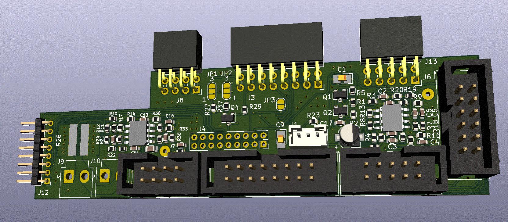
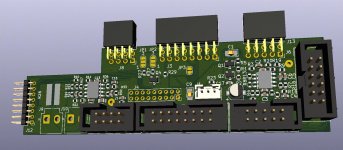
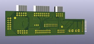
and I teamed up to design a plug in board for the Hypex Fusion plate amp. It uses the ADAU1777 dsp in the feedbackloop and the amp is used in current mode.

Intro RMS-Acoustics & Mechatronics
and I teamed up to design a plug in board for the Hypex Fusion plate amp. It uses the ADAU1777 dsp in the feedbackloop and the amp is used in current mode.
Attachments
I don't think I ever read a more coherent explanation of motional feedback. Thanks for link. Is the Hypex add-on board reviewed and ready to ship?At this moment Rob
Intro RMS-Acoustics & Mechatronics
and I teamed up to design a plug in board for the Hypex Fusion plate amp. It uses the ADAU1777 dsp in the feedbackloop and the amp is used in current mode.
And I still can't figure out if a voltage amp with MF is any different than a current amp with MF? The old principle is that the feedback loop determines system behaviour.
But for the DIYer, there remains the great question of choice of sensor. For sure, attaching a mechanical accelerometer is trickier* than working with back-EMF electrically. But if the electrical/magnetic inhomogeneities are bigger than the mechanical ones, you need to sample the cone mechanical output rather than rely on a current sensor or bridge.
B.
*Seems like accelerometer attachments are hard to do right, as in the link's artifact at 1.8kHz, and other issues (including cost).
But if the electrical/magnetic inhomogeneities are bigger than the mechanical ones, you need to sample the cone mechanical output rather than rely on a current sensor or bridge.
Since the vast majority of "nonlinearities" (not inhomogeneities) are electrical using EMF feedback is not a viable choice. This is because the EMF has the nonlinearities squared (back EMF is proportional to BL^2 and so if the BL is nonlinear then the EMF nonlinearity is the square of the BL nonlinearity.) Hence, the harmonics in the back EMF are not the same as the harmonics in the cones actual motion.
Since the vast majority of "nonlinearities" (not inhomogeneities) are electrical using EMF feedback is not a viable choice. This is because the EMF has the nonlinearities squared (back EMF is proportional to BL^2 and so if the BL is nonlinear then the EMF nonlinearity is the square of the BL nonlinearity.) Hence, the harmonics in the back EMF are not the same as the harmonics in the cones actual motion.
That is an incontestably good arm-chair footnote, esp. when the world can be neatly divided into the linear and the nonlinear.
Except for extreme motions, I'd guess that not much evil arises from irregularities of the magnetic circuit. And like other easily overlooked problems in sound reproduction, it is low-level signals that need to be real good not the more typically reported extremes of performance (for example cross-over distortion in complementary transistor amps).
So squared or not, is it inhomogeneities of the mechanical suspension, cone vibrations, and acoustic influences that we need to address using feedback? For example, there's gotta be hysteresis and stiction and issues that bedevil the spider and surround at the tiny sound level motions we listen intently to.
Frankly, I would like to see data on where irregularities of sound propagation arise in Rice-Kellogg cone drivers. Only then could we posit that electrical or mechanical sensors are better.
B.
Last edited:
So squared or not, is it inhomogeneities of the mechanical suspension, cone vibrations, and acoustic influences that we need to address using feedback? For example, there's gotta be hysteresis and stiction and issues that bedevil the spider and surround at the tiny sound level motions we listen intently to.
Yea, this is the same old stuff - not true, nothing there. And there is that totally inappropriate word "inhomogeneities". Show me that word in any mechanics texts (not materials - it applies to materials not mechanics.) The material can be "inhomogeneous" and still be completely linear. And I have never seen hysteresis or stiction in a typical driver. You would have to show this to me .
Yea, this is the same old stuff - not true, nothing there. And there is that totally inappropriate word "inhomogeneities". Show me that word in any mechanics texts (not materials - it applies to materials not mechanics.) The material can be "inhomogeneous" and still be completely linear. And I have never seen hysteresis or stiction in a typical driver. You would have to show this to me .
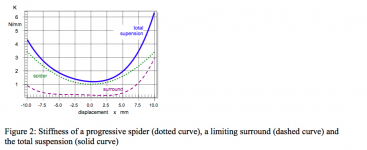
Trying googling "hysteresis" and "loudspeaker" and a bunch of links show up (some about magnetic hysteresis too). For example, if you google "hysteresis", "loudspeaker" and "klippel" (a famous name), you get a paper with the figure below.
Sorry, Earl, didn't mean to embarrass you, but you did say "show this too me".
B.
PS. As someone who testifies in court from time to time, I avoid using a term like "linear" in my Opinions unless I was prepared to defend it in every way. I would use a common-parlance word like "irregular" which covers all kinds of stuff but says what I mean. Here I can say "inhomogeneity" for fun value, present company excepted, and because it really does denote in one plain word all kinds of error, whether you or I know what all of these errors are right now.... so it says just what I mean. It is a common fallacy to believe that a fancy techno-word is always more precise than a plain word.
Attachments
Last edited:
Ben
That curve does not show hysteresis or stiction. It is simply a nonlinear stiffness which for small displacements will not have any significant audible effects. Let's keep on track here, we were talking about nonlinearity at small displacements, not large ones. I agree that stiction, if it occurred, would have this effect, but I have never seen it in practice and your example does not show it either. I am not convinced that hysteresis has small displacement effects.
I am more than aware of Klippel's work and his paper makes no reference to what you are saying.
I too have been an Expert Witness on many occasion and I would never avoid using the proper term "linear" as it is the correct mathematical term to use.
Just below the figure I posted above, Klippel says,I am more than aware of Klippel's work and his paper makes no reference to what you are saying.
"In response to a slow ac-force the displacement generally follows with a hysteresis caused by losses in the material."
I don't know whether the factor is large or small. Lots of things I don't know and I try to admit it.... when absolutely necessary.
Gosh, Earl, I don't think you are talking with the prudence an Expert Witness should demonstrate.
B.
I don't know whether the factor is large or small.
Which is precisely what I have been saying - it's small, negligible.
Is this discussion relevant in this topic?
It is relevant because different feedback sensors correct different errors. So you've got to know which errors you want to address.
In the case of suspension irregularities, both electric and acceleration feedback work. In the case of cone breakup, neither electric nor acceleration feedback works.
For inhomogeneities of the magnetic motor, acceleration works but electric not as well maybe.
There are also the inside-versus-outside pressure and microphone (glued to cone and near-field) sensors. And the various influences of voltage or current amps.
B.
One way to avoid worrying about bad-tempered magic unicorns biting our toes while we sleep at night is to check for unicorn spoor, and finding none, ease our worries. ")
Back in 1998 or so when I was working on an MFB woofer, I attempted to make THD measurements using an actual measurement microphone placed near the woofer. I have forgotten exact details, but I remember that appreciable THD only appeared at low frequencies and large cone excursions. (No unicorn spoor was found, in other words.)
Picking that apart a little bit:
1) There was no evidence of "sticky" motion at big or small amplitudes.
2) The total force on the moving parts of the speaker is the sum of inertial forces (Newton's "ma"), and constraint forces from the spider and surround, which we can expand in the usual Taylor power series in displacement (f = -k1 x - k2 x^2 - k3 x^3, where "x" is the displacement, k1, k2, k3 are coefficients.) We can expand the force from the voice coil in a similar Taylor series.
The key point is that at frequencies appreciably above the fundamental speaker resonance f0, the inertial forces ("ma") are much bigger than the spider/surround spring forces. The inertial forces are perfectly linear, so as frequency goes up above f0, these perfectly linear inertial forces increasingly overpower the nonlinear forces from the suspension. If f0 is, say, 30 Hz, then the inertial forces are 100 times bigger than the forces from cone suspension by the time you get to 300 Hz. For this example, even the worst imaginable suspension would only manage to contribute 1% nonlinearity at 300 Hz.
By contrast, at f0, inertial and suspension forces are equal. A nonlinear suspension can really affect cone motion.
Below f0, suspension forces are bigger than inertial forces. Now the suspension nonlinearity dominates the cone motion.
It's been a long time, but my memory is that, with the woofer mounted in a sealed box, I measured considerably in excess of 10% THD - mostly 3rd harmonic - at large cone excursions, at frequencies well below the fundamental resonance of the speaker/sealed box.
My memory is that I eventually managed to get a maximum of 18 dB of negative feedback at the peak frequency of the open-loop response, and this produced nearly the theoretical 18 dB of THD reduction. In other words, THD fell to not much more than one-tenth of its non-servo'd value at this frequency.
Once I got past the two tricky bits - developing the accelerometer itself, and managing the phase margin at the HF end - the servo system was docile, polite, behaved like the text-book equations said it would, and showed no irritable-unicorn characteristics at all.
To me, the nice things about servo feedback - implemented properly with a sensor on the moving parts of the speaker - is that it (a) really reduces THD at low frequencies, (b) really flattens the frequency response, and (c) makes the system insensitive to small changes in box volume, room temperature, etc.
For a one-off DIY build, the big downside, for me, is the additional mass of a home-made accelerometer + voice coil mount. That, and the need to make multiple frequency and phase measurements in order to design the servo loop shaping.
-Gnobuddy
Never much to add after Gnobuddy has posted and as lucidly as could be. But some emphases might be made.
Once over 100 Hz or so, MF (as we know it today) is trouble to sort-out and the benefits are modest. It is the region near speaker resonance and below that subs need the most help* and MF provides the most benefit.
At the risk of alienating the mathematically inclined, I'm not sure HD tells the whole story, perhaps if only in the sense of "HD as we measure it". With MF greatly enhancing "fast" and "tight", can that performance be evaluated by HD of frequency sweeps?
Glancing at an amp playing square waves on a 'scope is vastly more illuminating than a frequency sweep, even if a Fourier analysis would kind of say the same thing. Likewise for physically examining cone motion on transients as compared to HD.... not to mention the testimony of your ears.
Another example of the bees-can't-fly variety: hard to prove with measurements that ESLs ought to sound superior to cone drivers but pretty obvious to the ear.
In my studies of MF in 1967, I used a storage 'scope and a triggered Polaroid camera in the Bell Labs anechoic chamber. Primitive, eh, but the best at the time. I looked at pulses. Dramatic differences plain to see with MF operating. Dramatic.
B.
* just nuts that we try to reproduce sound using a system with a big resonance inside the band
Last edited:
Oh, I don't think it does - but it does tell us if the various hypothetical "very non-linear at small excursion" behaviours exist: hysteresis, sticktion, et cetera. If there is little THD at small cone excursions, then we know that these behaviours don't exist, and we don't need to worry about them.I'm not sure HD tells the whole story
And that's more or less what I found - little THD at small excursions. And much more THD at large cone excursions.
Which is the behaviour we'd expect if cone suspension and magnetic forces were linear for small excursions, and progressively less linear for bigger excursions - just like the Taylor series expansions I wrote down earlier. I didn't find any evidence to suggest that the restoring force on the cone *at the present time* depended on something that had happened to the cone *in the past*, i.e. no hysteresis, etc.
I think near-field frequency response does indeed tell you pretty much everything about near-field impulse response, at least at frequencies low enough for the entire cone to be acting as one rigid piston.With MF greatly enhancing "fast" and "tight", can that performance be evaluated by HD of frequency sweeps?
Much further away in the room, I think all bets are off. If we position our woofer badly so that it excites a rather high-Q room acoustic mode, it takes time to build up energy in that mode, and time for it to die away. So the woofer cone may be "fast and tight", but the air in that room mode will build up more slowly to max amplitude, and then also die away slowly. So if our ears are in a region where that mode is strongly present, we might hear slower and boomier bass.
Maxell used to make a few sound-cancelling headphones that included a tiny microphone capsule in each ear-cup, and actual motional feedback. While the intention was to subtract away external acoustic noise in the environment, the side-effect was to also subtract away unwanted noises made by the headphone diaphragm itself. I loved the crisp, tight, extended, bass from those headphones, though the actual noise-cancelling feature was only marginally useful IMO.
As Murphy's Law dictates, inevitably Maxell stopped making that (those?) models, and instead went to a cheaper DSP solution rather than actual motional feedback. Gone is the wonderful bass performance of the old models.
I tend to agree, but fortunately, our ear/brain is rather forgiving at low frequencies. The big bass drum sounds like a drum even when the drummer forgot to tension the drumhead optimally.* just nuts that we try to reproduce sound using a system with a big resonance inside the band
-Gnobuddy
HD is not correlated to perception so as far as what we hear matters HD (or THD or IMD) doesn't tell us a thing. On the other hand "fast" and "tight" don't have any useful definitions in audio that I know of, so they aren't much help either.At the risk of alienating the mathematically inclined, I'm not sure HD tells the whole story, perhaps if only in the sense of "HD as we measure it". With MF greatly enhancing "fast" and "tight", can that performance be evaluated by HD of frequency sweeps?
* just nuts that we try to reproduce sound using a system with a big resonance inside the band
A big resonance inside a band which has hundreds or thousands of acoustic resonances - what's one more?
My experience has been that a good speaker usually sounds better than a bad speaker, even in an unusually "live" room with lots of poorly controlled acoustic resonances. Somehow, our ear/brain mechanism can separate nasty resonances in the room from nasty resonances in the speaker itself, at least to some extent (for this to work, you have to be receiving a fair amount of direct sound from the speaker at your ears.)A big resonance inside a band which has hundreds or thousands of acoustic resonances - what's one more?
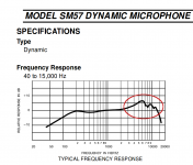
Speaking of nasty-sounding resonances within the audio frequency range, the attached image shows a famous audio transducer that is the worlds best selling model in its category. As you'd expect from the multiple nasty, poorly controlled resonances seen in its frequency response, it sounds utterly horrid.
Astonishingly, hardly anybody seems to notice how bad it sounds, and it continues to be a best-seller, literally the most popular device of its type.
-Gnobuddy
Attachments
- Home
- Loudspeakers
- Subwoofers
- Commercial motional feedback woofer available sort of