32' rank is 16Hz, 64 would be 8Hz. Several dispositions do have 32' flutes or diapasons which will have a pretty good fundamental.
Understand, most 64' stops use a 32' and a 21 2/3' to make a fake 64. Many 32' stops do the same type of thing.. If you play mainly 32's -- It might be worthwhile to take your output, loop it back and run an RTA on it to verify what your stops are really doing, and then build your subs to match.
In the sample sets I have seen there are some examples of direct sampled 32' stops but many are done by frequency shifting of 16' samples. In any case they are generating tones in the 16Hz range.
Even if done by combining stops it would seem that the resultant frequency would still appear at the speakers as long as the mixing were done electronically (either digital or analog). Am I missing something here? It seems to me that the only way to avoid having to reproduce the actual frequencies would be to have one speaker generating the fundamental (16') pitch and another one generating the quint and allow the mixing to occur acoustically. One could do this I suppose but I am not aware of this method being used in VPOs.
As much fun as it might be, I wouldn't really have any interest in generating a 64' rank as I don't think it would really be useful.
Since one of the memory slots died on my VPO computer I am limited in what I can do (can't really play anything) until I get a replacement. However I will try to see if I can get it to load a smaller organ like the Mockers and the spectrum analyzer at the same time and check out the 32 on it. Otherwise I may be able to create a test disposition with only the one stop if (big if) I have enough working memory to import the SF file.
Will report back if I find out anything. And yes, 32Hz is trivial.
Will report back if I find out anything. And yes, 32Hz is trivial.
I was able to get Mockers to load along with the spectrum analyzer. The analyzer only goes down to 20Hz but I was able to determine that with the Subbass 32' on, the fundamental on the second "C" is a strong 32Hz so the low "C" would indeed be 16Hz.
Just in case they might play games with the last octave I went ahead and ran down the C major scale and the fundamental stepped down as expected until it went off scale. Even on the low "C" I could still see a tiny bit of the right side of the trace of the fundamental.
It would be possible to create our own Resultant 32' by using a quint (very easy to do in jOrgan) but the result would probably be less satisfying than the real thing.
One thing that might give us a little bit of wiggle room is that the horn can be tuned a little bit higher than 16Hz (actually I believe the actual frequency is 16 point something) as long as it doesn't unload enough to damage the driver and still provides enough output to be useful.
The opening into the room from the chamber is 6' wide by about 5' high on one side and about 6' or 7' high on the other however back from the opening a few feet we have at least 8' or 9' of width. So a stack of up to four horns (front, back, tapped or whatever) could be accommodated up to 8'x6'.
The chamber in which I plan to put the pedal and great division has an electric overhead screen several feet in front of it leaving only a couple of feet of the opening above the screen. I assume that the sub-woofer would have no problem with this and the smaller speakers could be installed in such a way as to allow them to speak over the screen. Getting an acoustically transparent screen is a possibility as well.
Do you have 8' tall? aka a quad of up/back TH that's 8' tall by about 20"x24"
Yea, it's usually only the bottom 1/2 octave or bottom octave they play with -- but I think your RTA test, where you could see a 'bit' of the fundamental on your C tells us it's real, not phantom..... I guess there is a reason many of these organ installs are infinite baffle.
Yea, it's usually only the bottom 1/2 octave or bottom octave they play with -- but I think your RTA test, where you could see a 'bit' of the fundamental on your C tells us it's real, not phantom..... I guess there is a reason many of these organ installs are infinite baffle.
For a look at the target installation see here...
Small VO project Inspiration from larger installation
I think you need to be registered (free) to see the pics. If you don't want to do that here are a couple of pics to give you an idea.


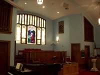
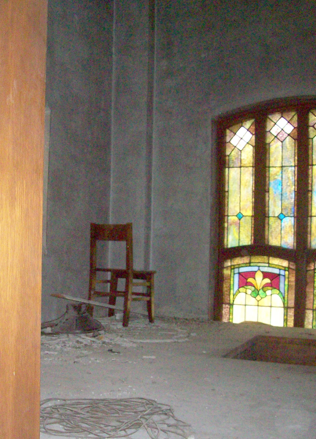
In the first picture you can see the square pattern lattice across the bottom of the openings. They look to be about 1 foot square and there are six across the bottom so the width is about six feet so you can get an idea. The rooms behind fill the entire area from the loft to the outer walls so the space is pretty large. Quite a bit of room for a stack. Original experiments used a pair of 1x15" PA speakers in the right hand chamber and a cludged together 2x12" sub under the keyboards that I was using. It did a credible job of filling the room if care was taken not to get too excited.")
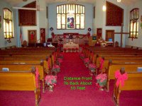
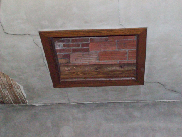
In the second picture you can see the screen (retracted) behind the light fixture on the left.
Building construction is brick and I think that they are plaster on lath walls but I am not sure.
Small VO project Inspiration from larger installation
I think you need to be registered (free) to see the pics. If you don't want to do that here are a couple of pics to give you an idea.
In the first picture you can see the square pattern lattice across the bottom of the openings. They look to be about 1 foot square and there are six across the bottom so the width is about six feet so you can get an idea. The rooms behind fill the entire area from the loft to the outer walls so the space is pretty large. Quite a bit of room for a stack. Original experiments used a pair of 1x15" PA speakers in the right hand chamber and a cludged together 2x12" sub under the keyboards that I was using. It did a credible job of filling the room if care was taken not to get too excited.
In the second picture you can see the screen (retracted) behind the light fixture on the left.
Building construction is brick and I think that they are plaster on lath walls but I am not sure.
Attachments
Go IB, add watts, don't break the plaster.
start with a quad of these.
http://www.parts-express.com/pe/showdetl.cfm?partnumber=295-455
start with a quad of these.
http://www.parts-express.com/pe/showdetl.cfm?partnumber=295-455
Last edited:
Interesting that you should mention that driver. I looked at it some time ago as an IB.
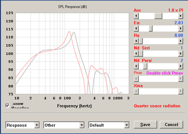
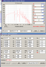
It seems to like a TL even better. No need for EQ in the TL and maybe a couple DB more output.
The distortion might be better with IB but I am not sure once you add the EQ. Might need 8 drivers for IB. Four drivers gives about 135dB Max SPL in the TL v.s. 116dB in the IB (x-max limited). 8 IB gives about 122dB. Might even be able to get away with two in TL.
BTW, I really appreciate your help.
Attachments

It seems to like a TL even better. No need for EQ in the TL...
Still not counting on any room gain at all? That response might sound boomy in-room if you don't eq the low end down. If I were you I'd measure the room's response before going too much farther.
4 sided manifold for the IB. 2 magnets in and 2 magnets out. push pull.
You have the perfect place to put the manifold, it's the 'tried and true' approach others have used for organ.
As much as I'm a fan of TH's, etc... after seeing your pictures, I would have a very hard time not going IB.
You have the perfect place to put the manifold, it's the 'tried and true' approach others have used for organ.
As much as I'm a fan of TH's, etc... after seeing your pictures, I would have a very hard time not going IB.
Still not counting on any room gain at all? That response might sound boomy in-room if you don't eq the low end down. If I were you I'd measure the room's response before going too much farther.
To be honest I wouldn't expect much room gain in a room that is about 50,000 cubic feet that has an entire wall open to another room that is probably another 10,000 or 15,000 cubic feet which is open to the stairway down to the entry way... I am no expert though so I could be all wet.
As we get closer to cutting wood (in other words as funding becomes available) I will see about nailing down the room response. If I can't get good measurements I can always knock up a big box with a couple of drivers in it and see what I get. I presume that one of those Behringer measurement mics with some freeware would be all I would need to get a close enough idea of the room response.
4 sided manifold for the IB. 2 magnets in and 2 magnets out. push pull.
You have the perfect place to put the manifold, it's the 'tried and true' approach others have used for organ.
As much as I'm a fan of TH's, etc... after seeing your pictures, I would have a very hard time not going IB.
I like the idea of IB for its elegance and potential for low distortion. What scares me is all of the reading I have done which indicates that guys end up needing four or more such drivers just for their little living room. It makes me wonder about filling a room literally and order of magnitude larger.
Interestingly my recollection of the original Dayton IB was that it had a higher Qts than the current one which seems a bit on the low side for the application. One possible approach would be IB using the FI 18IBs which have slightly higher Q and twice the x-max. They are about $100 more per driver last time I checked but four drivers should reach 123dB at 16Hz at 1 meter.
If I got the Datons and they proved inadequate they could always be used as very capable woofers for the 16' and 8' ranks on the manual divisions so getting some to try would be low risk.
To be honest I wouldn't expect much room gain in a room that is about 50,000 cubic feet that has an entire wall open to another room that is probably another 10,000 or 15,000 cubic feet which is open to the stairway down to the entry way... I am no expert though so I could be all wet.
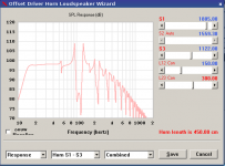
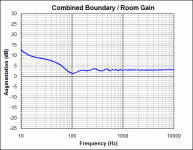
I've got no experience with very large rooms either so I ran the numbers. Pressure gain is not as strong as I expected.
This simulation accounts for pressure gain and estimated power response of the 3 nearest boundaries, and suggests a bit more gain than a 1 pi simulation in Hornresp.
Attachments
Last edited:
So, regarding the manifold IB, I was wondering what effect the manifold would have on the parameters/alignment of the woofers. It seems that just like the rear chamber has an effect the manifold ought to as well. I would like to hear from anyone who has investigated that.
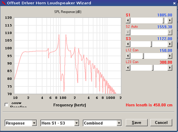
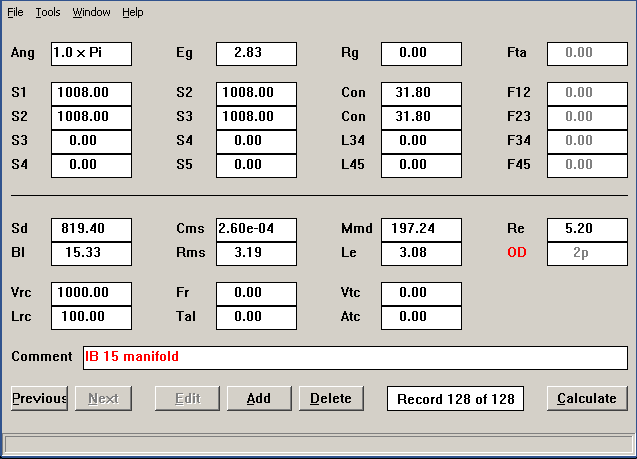
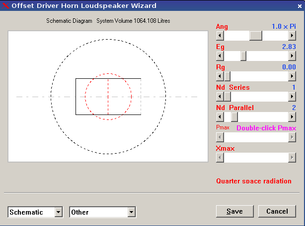
I thought that maybe I would try to model it so I set up Hornresp with a large sealed rear chamber in a short straight horn with offset drivers as my best first try at modeling it. Of course it doesn't model the two drivers firing into each other but it was the best thing I could think of off of the cuff. Is there a better way to model this.
Would you place the manifold on the floor of the chamber close to the outside wall at the front of the chamber or would it be better to place it in the back outside corner of the chamber. The ambiance of the rear of chamber location would not be a bad thing in the case of an organ but I am wondering if the increased output would be negated by the increased distance (about 10 feet) and absorption in the chamber. Although the chamber walls are bare plaster and brick...
P.S. I also noted that by opening up the manifold into a Vee like shape (opening larger than the back of the manifold) it tames the huge spike in the output above 100Hz.
Attachments

Last edited:
Hmmm... Traditional MLTL seems to give one a lot of control over the slope. In playing with this alignment I discovered that the enclosure is very tunable so that the slope can easily be matched to the actual room acoustics. That is an attractive feature and two enclosures with Dayton IB15 may be sufficient.

Attachments
The way you model seems correct.I thought that maybe I would try to model it so I set up Hornresp with a large sealed rear chamber in a short straight horn with offset drivers as my best first try at modeling it. Of course it doesn't model the two drivers firing into each other but it was the best thing I could think of off of the cuff. Is there a better way to model this.
Would you place the manifold on the floor of the chamber close to the outside wall at the front of the chamber or would it be better to place it in the back outside corner of the chamber.
P.S. I also noted that by opening up the manifold into a Vee like shape (opening larger than the back of the manifold) it tames the huge spike in the output above 100Hz.
"V" shapes do seem to be less peaky than parallel wall plenums.
If you do decide on IB, I'd suggest flush mounting at the front of the chamber for a smoother frequency response.
Seems that the chamber itself could be used for the outer walls of a horn, you would only need to build a small portion of a rather giant horn.
Hmmm... Believe it or not I never thought of doing a corner horn in the chamber... (need a :scratchchin: emoticon here). The walls are about 8 or 10 feet I suppose. I would have to cover the windows I suspect. Will have to cogitate on that a little bit and see how one might model and build such a beast.
When I first considered IB I thought of running a floor to ceiling manifold exhausting into this attic opening in the ceiling of the left hand chamber.
In any case I am concerned about the cracking plaster. My fear is that a large amount of bass energy could bring the house down - so to speak. For this reason I am inclined to stick with sub-woofers at the front of the chamber firing directly into the sanctuary space to avoid damage.
Attachments


Would be rather an expensive mistake to take one of those out. What I will probably end up doing as soon as I get a VPO computer back on line is to build a 30Hz sub using a 15" that I have on hand and move it around to different locations to do some experimentation (limiting myself to 16' pedal stops).
The only place I see where there is enough contiguous wall space on both sides of a corner for a corner horn is in the choir loft and that might be a bit painful for the choir members. Similarly firing through the side openings of the chambers into the loft for resonance purposes would be problematic. So at the front of a chamber or on the floor in the corner at the front of the sanctuary are probably the only real options.
As to taking room modes into account my current thinking is to design the subs for flat into 1-pi space and use eq to reduce the low bass output if needed rather than design compensation in and possibly have to boost. My thinking is that a simple 1st order filter at the input of the power amp should be adequate to handle any boominess if it shows up and cutting the low bass frequencies will conserve power amp headroom as well as reduce any low frequency noise as opposed to running amps flat or boosted. This also increases max SPL as I get a bit more output for the same x-max.
What I will probably end up doing as soon as I get a VPO computer back on line is to build a 30Hz sub using a 15" that I have on hand and move it around to different locations to do some experimentation (limiting myself to 16' pedal stops).The only place I see where there is enough contiguous wall space on both sides of a corner for a corner horn is in the choir loft and that might be a bit painful for the choir members.
Similarly firing through the side openings of the chambers into the loft for resonance purposes would be problematic. So at the front of a chamber or on the floor in the corner at the front of the sanctuary are probably the only real options.As to taking room modes into account my current thinking is to design the subs for flat into 1-pi space and use eq to reduce the low bass output if needed rather than design compensation in and possibly have to boost. My thinking is that a simple 1st order filter at the input of the power amp should be adequate to handle any boominess if it shows up and cutting the low bass frequencies will conserve power amp headroom as well as reduce any low frequency noise as opposed to running amps flat or boosted. This also increases max SPL as I get a bit more output for the same x-max.
- Status
- This old topic is closed. If you want to reopen this topic, contact a moderator using the "Report Post" button.
- Home
- Loudspeakers
- Subwoofers
- Virtual Organ Stacked Horn Sub Questions