You both said that I am wrong yet then both proceed to agree with what I said.")
Patrick seemingly said that isobaric loading a pair of drivers cuts excursion in half for the same given output level as a single identical traditionally loaded driver. It does not. You do not gain any maximum displacement limited output over a single driver by using two identical drivers in isobaric. You are not utilizing the SD of both drivers for output, only one and driver mechanical stroke is not changed therefore total displacement potential does not increase.
In a standard configuration you gain 6dB by doubling the drivers (total displacement) but in isobaric you are not doubling the total displacement since half of the driver radiation is not coupled to the outside. Effectively you are combining both motors to the SD of a single driver with an isobaric config essentially creating the same driver as before with a much more powerful motor. I just don't want anyone who may be reading to get confused and believe that they will get significant increases in headroom by using isobaric driver configurations because they won't. Using the second driver conventionally will allow for 6dB of potential headroom over a single. Isobaric does not. That would be getting your cake and eating it too and it just doesn't work like that.
EDIT: I see that the comparison is of 4 drivers isobaric versus a single conventional in order to gain the 6 dB Patrick was mentioning. I missed that part. That is correct. You need 4 drivers to 1. You sacrifice 6dB potential by isobaric loading. How often is it that a real world build will be able to cram 4 drivers into a smaller space than 1 would work especially in a horn which is usually crammed to begin with? Not to mention 4x the driver cost and weight for any actual increase in performance over a single driver. Typically it makes more sense to just take the increased budget for the 4 drivers and upgrade to a much more powerful, larger or higher displacement unit to begin with and keep the build complexity down.
Last edited:
I think I'll leave this here
So much for the collective Josh
An externally hosted image should be here but it was not working when we last tested it.
So much for the collective Josh
Or try this Patrick, if you insist in searching a way that might beat a TH. It will only take two drivers;
An externally hosted image should be here but it was not working when we last tested it.
Oops, that was the wrong picture;
;An externally hosted image should be here but it was not working when we last tested it.
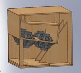
I spent a short time today playing around with isobaric TH design.
It would be possible to fit 8 10" drivers into a Cubo sub
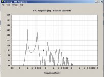
Unfortunately the Hornresp sim is very ugly in 8 X isobaric mode!
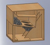
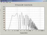
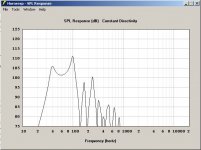
Looks OK with 4 conventional drivers though.
Cab is Cubo sub as on freespeakerplans Home
Driver was B&C 10NW64
This is at 2.83V with all of the drivers in parallel
Regards Xoc1
It would be possible to fit 8 10" drivers into a Cubo sub
Unfortunately the Hornresp sim is very ugly in 8 X isobaric mode!
Looks OK with 4 conventional drivers though.
Cab is Cubo sub as on freespeakerplans Home
Driver was B&C 10NW64
This is at 2.83V with all of the drivers in parallel
Regards Xoc1
Attachments
Your very quick drawing does not look like a tapped horn, and is not an isobaric loading.how about the 'symmetric' version with two drivers in the middle, playing against each other, and two port openings, one each side ?
very quick drawing
What is your "question" asking?
The arrangement you show in post #28 uses a lot more wood to achieve a given path length than the fold patterns similar to the DSL TH-115 or 118.better ?
I fail to see anything "better" about that feature, unless you prefer cabinets to be heavier, more expensive and larger for a given Fb.
Last edited:
No, it doesn't.The arrangement you show in post #28 uses a lot more wood to achieve a given path length than the fold patterns similar to the DSL TH-115 or 118
Each layout has it's own set of limitations and benefits but a testcase I did came up with a difference between the two, within 1%. if you want a cabinet that is very high or deep I think Tinitus setup is a good way to achieve that.
In other news:
A problem arising from the isobaric setup is that the compression ratio is set to a minimum resulting from the driver depth, which is usually larger then the compression ratio needed or wanted. One way around it, is to use a chamber volume at the beginning of the horn.
@Xoc1: Once got the inquiry for a Cubo 15 to be isobaric. However since it made the difference between a 10 kg driver or a 20 kg "driver", I advised against it.
Also from a more designer technical point of view, an isobaric setup only needs half the chamber volume in comparison with the single driver. To keep performance and internal volume equal that would mean that half the chamber volume needs to be converted to extra horn length to meet the T/S-parameters of the isobaric setup.
That means that a isobaric Cubo without change will need a driver that is less optimal, for instance because the Vas is orignally to large. Or in other words a driver that would in single arrangement need a much larger chamber.
Best regards
Johan
No, it doesn't.
Each layout has it's own set of limitations and benefits but a testcase I did came up with a difference between the two, within 1%. if you want a cabinet that is very high or deep I think Tinitus setup is a good way to achieve that.
In other news:
A problem arising from the isobaric setup is that the compression ratio is set to a minimum resulting from the driver depth, which is usually larger then the compression ratio needed or wanted. One way around it, is to use a chamber volume at the beginning of the horn.
A few thoughts on this:
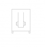
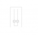
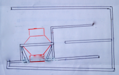
1) I realized that going isobaric with a tapped horn is tricky, because you can't achieve a high compression ratio at the throat. The way to get around this is to 'slide' the drivers apart from each other.

Kinda like this, but with one woofer inverted. Keep in mind you can make that gap ultra-small, even a quarter of an inch.
2) Most of the 'compelling' isobaric designs that I've come up with use car audio and home audio drivers. They tend to have a lower FS and higher qts than prosound drivers, and due to this, require surprisingly large boxes. The tapped horn that I used to have my Diyma 12s in was something like thirteen cubic feet for two woofers.
3) Simply cramming the woofers into the box gets to be a problem. Might be best for tapped horns that dig down to 20hz, as those boxes tend to get hyooge.
...
... Keep in mind you can make that gap ultra-small, even a quarter of an inch. ...
Unfortunately, you can't. The duct between the drivers has to have a cross-sectional area approaching the Sd of the driver. And the extra volume between the drivers worsens the excursion difference I described earlier.
Originally posted by Weltersys:
The arrangement you show in post #28 uses a lot more wood to achieve a given path length than the fold patterns similar to the DSL TH-115 or 118.
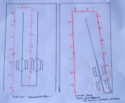
Tinitus' "symmetric version" uses double the interior wood needed for the same path length as can be seen in the left drawing.
Getting a high compression ratio with an isobaric loading is easily achievable by with a reduction chamber as in the right drawing.
The arrangement you show in post #28 uses a lot more wood to achieve a given path length than the fold patterns similar to the DSL TH-115 or 118.
Johan,No, it doesn't.
A problem arising from the isobaric setup is that the compression ratio is set to a minimum resulting from the driver depth, which is usually larger then the compression ratio needed or wanted. One way around it, is to use a chamber volume at the beginning of the horn.
Tinitus' "symmetric version" uses double the interior wood needed for the same path length as can be seen in the left drawing.
Getting a high compression ratio with an isobaric loading is easily achievable by with a reduction chamber as in the right drawing.
Attachments
Hi Y'all,
This opens a whole "new" field of possibilities:
Regards,
I'm confused. I see you draw the surface area. I always thought the cone correction was to compensate for the volume the cone/driver has. So now I'm confused why you don't calculate the cone/driver volume to be compensated.
Johan,
Tinitus' "symmetric version" uses double the interior wood needed for the same path length as can be seen in the left drawing
and makes the baffles less 'ressonant'
anyway, I have dropped isobaric for now
the woofer I'm looking at now is more expencive quality woofer
so..only one woofer to begin with, or at least until tested
maybe I could just as well use a cheaper Beyma, but I like the idea of having 'alternative options' later on
but there is one alternative to isobaric
and I suppose noone really needs the advantage of using half the volume, so...
basicly you just reverse one of the two woofers...magnet in and magnet out...push pull
and I suppose its been done many times already
question is if there is anything to gain from this at all
so, one driver it is, for me
Hi Y'all,
This opens a whole "new" field of possibilities:
Regards,
Suggest some dimensions. I'll model it in AkAbak.

- Status
- This old topic is closed. If you want to reopen this topic, contact a moderator using the "Report Post" button.
- Home
- Loudspeakers
- Subwoofers
- Isobaric tapped horns