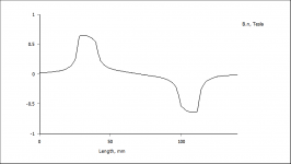
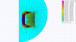
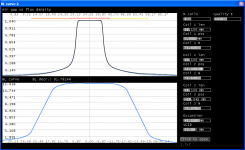
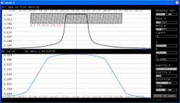
Please note when exporting flux data from FEMM, the (Normal flux density) curve must be used:
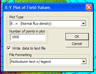
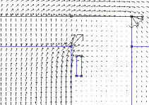
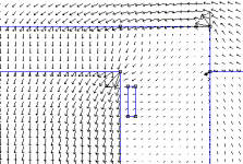
The exerted force felt by the coil depends on the direction (or angle) of the flux. This is the flux that is perpendicular to the coil. The straight is the tangential.
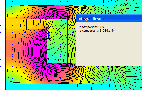
So, sqrt(perp^2 + tang^2) = magn of flux density and, angle = atan2(perp,tang)
Here is a short proof:
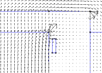
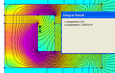
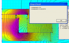
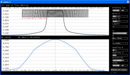
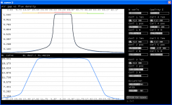
in the 1st image below the coil is put in a field where the angle is not perpendicular, therefore BL is just 0.22, in opposed to the 2nd image where the angle is more perpendicular, now BL is ~4.0. The next images show the directions when only the magnet/coil is enabled, respectively.


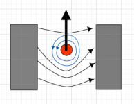
(this is how the force roughly looks like: )

Next time i will share the application and the details, how to use it etc..
The exerted force felt by the coil depends on the direction (or angle) of the flux. This is the flux that is perpendicular to the coil. The straight is the tangential.
So, sqrt(perp^2 + tang^2) = magn of flux density and, angle = atan2(perp,tang)
Here is a short proof:
in the 1st image below the coil is put in a field where the angle is not perpendicular, therefore BL is just 0.22, in opposed to the 2nd image where the angle is more perpendicular, now BL is ~4.0. The next images show the directions when only the magnet/coil is enabled, respectively.
(this is how the force roughly looks like: )
Next time i will share the application and the details, how to use it etc..
Attachments

Nice work.
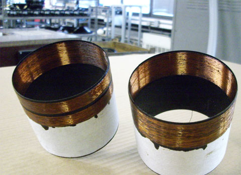
DDD coil:
Yup. That's it alright. Been a while Since I fixed up that WGTi.
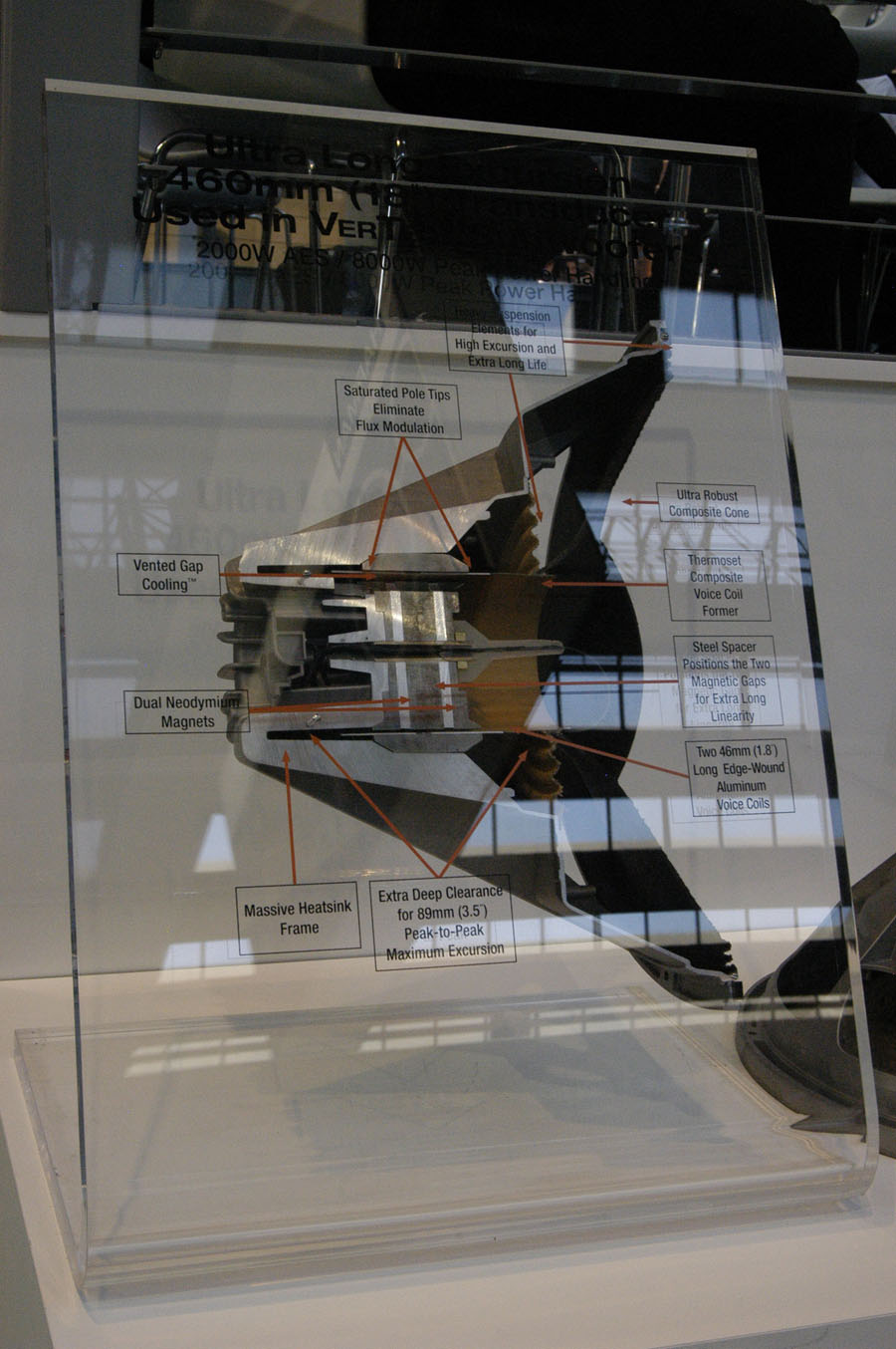
One thing I saw with that simulation of the DDD motor, is that the coils appear to be centered on each magnetic gap, where as in reality they are offset towards each other so that only the last 0.5" of each coil are within the physical measurement of each 0.5" gap. That's how it is for the mobile audio subwoofers anyhow.
Last edited:
Hi OscarS,
It's good to see someone who does reconing on subs.
There was a time when i was interested in getting bad/misadventurous subs and fix them. It's worth to do that. At least for their NEO structures.
Do you mean this way: ?

According to the simulations, the BL curve is not better. But i'm going to give it a try in FEMM, and see the real results of the evaluations.
Regards,
Akos
It's good to see someone who does reconing on subs.
There was a time when i was interested in getting bad/misadventurous subs and fix them. It's worth to do that. At least for their NEO structures.
Do you mean this way: ?
According to the simulations, the BL curve is not better. But i'm going to give it a try in FEMM, and see the real results of the evaluations.
Regards,
Akos
Attachments
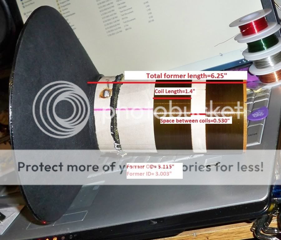
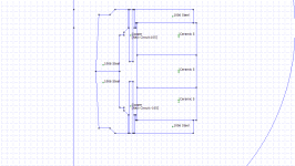
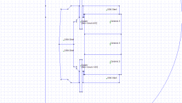
The issue I see with your model is that you don't have enough space between your magnetic gaps. Notice how there is 0.53" in between the 1.4" long coils on the former. With this spacing it allows the coils to be "inner hung" without having any windings outside of the magnetic caps. Here is what I'm talking about:
So to correctly model the W12 and W15 GTi subwoofers, you need to have the 0.5" long magnetic gaps 2.33" apart (on the inside). This places the gaps at the outermost end of each coil's last 0.5" worth of windings.
So to correctly model the W12 and W15 GTi subwoofers, you need to have the 0.5" long magnetic gaps 2.33" apart (on the inside). This places the gaps at the outermost end of each coil's last 0.5" worth of windings.
Wonderful. Absolutely wonderful.
Anybody read the book by the London student who tried to build a toaster from scratch (yes from copper ore, etc.)? Kind of a mess but a fun book.
I have often wondered about a Darwinian dead-end: "dynamic" magnets. Today, easy to make large, clean DC to power the magnet. Could these be more powerful or otherwise better than permanent magnets? (I won't even joke about the value of super-conducting magnets like in MRI and other applications.)
FWIW, when you are winding coils, you can create great motional feedback opportunities. THAT is the way to address distortion, not trivial improvements in pole piece geometry.
Ben
Thanks Dan,
OscarS, the application gives the same results as FEMM.
"FWIW, when you are winding coils, you can create great motional feedback opportunities. THAT is the way to address distortion, not trivial improvements in pole piece geometry."
I've heard that they're going to use HgBa2 for their new motor structures. It doesn't require as low temperature as the previous ones.
Why Modern subs have 2nd & 3rd harmonics of level around -30dB then? I assume they are well addressed.
The fun thing is that you can find those curves that were evaluated in JBL papers too. Sure they should have been moderated too. And of course they were crazy, and nasty just because they had been searched for the cure.
Thanks Dan,
OscarS, the application gives the same results as FEMM.
"FWIW, when you are winding coils, you can create great motional feedback opportunities. THAT is the way to address distortion, not trivial improvements in pole piece geometry."
I've heard that they're going to use HgBa2 for their new motor structures. It doesn't require as low temperature as the previous ones.
Why Modern subs have 2nd & 3rd harmonics of level around -30dB then? I assume they are well addressed.
The fun thing is that you can find those curves that were evaluated in JBL papers too. Sure they should have been moderated too. And of course they were crazy, and nasty just because they had been searched for the cure.
you're the expert. I was just laying out the differences.
")

OscarS,
Thanks for pointing out the differences.
I wish i could be
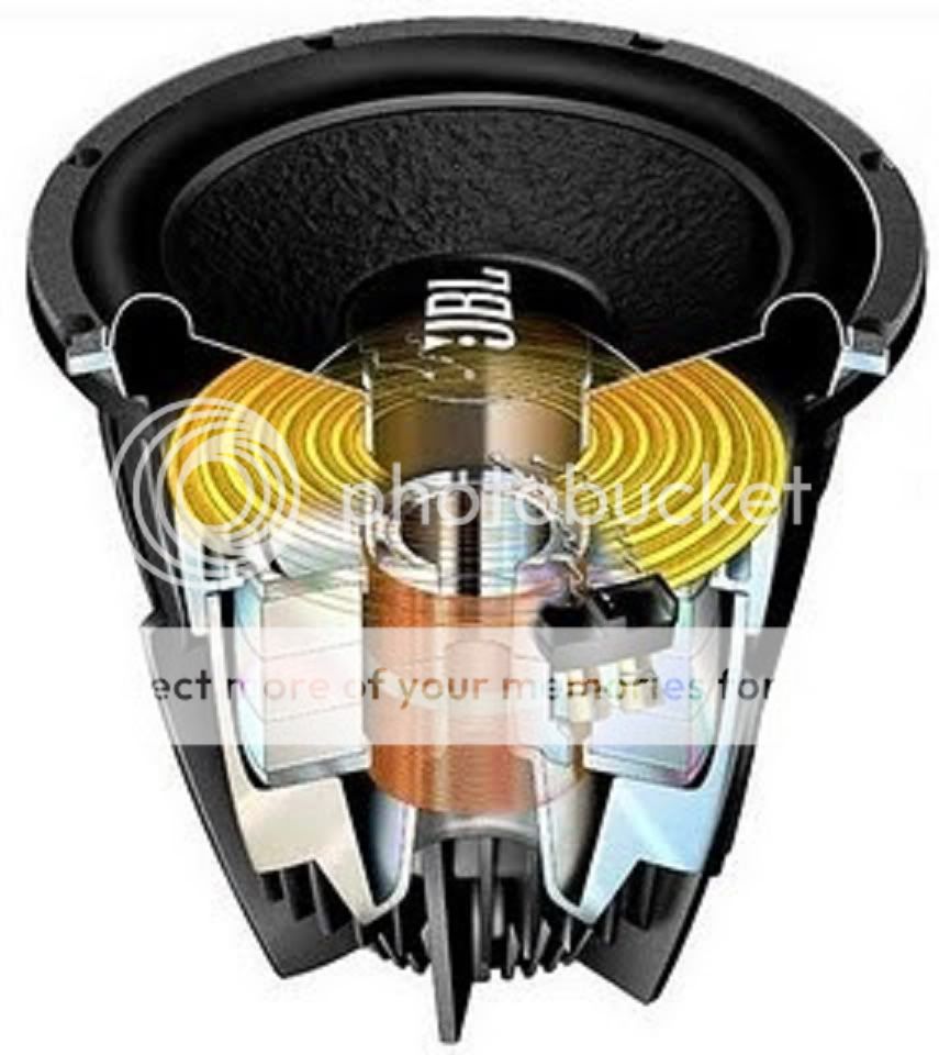
I did the modeling for the JBL wgti. In order to model the system right, it would be great to know how the structure looks like actually. This is just an approximation:


flux:

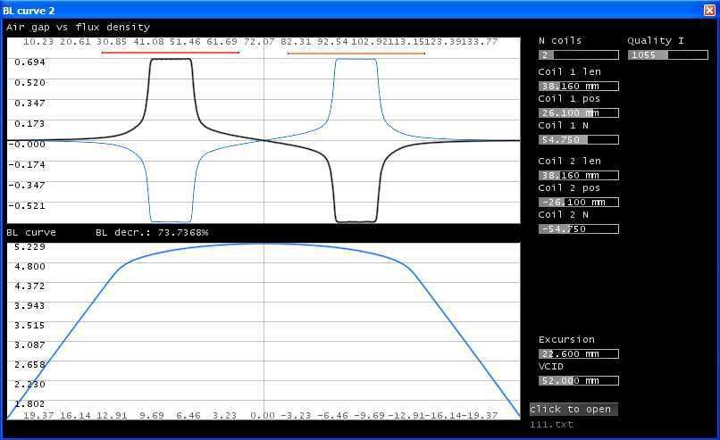
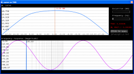
This is the BL curve given by FEMM:
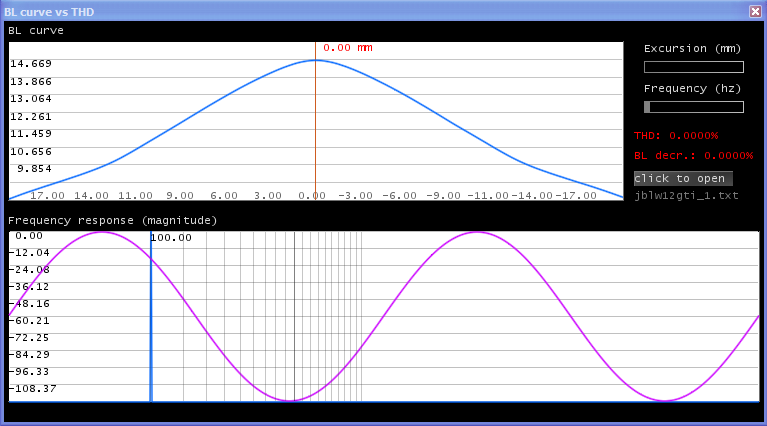
And the BL curve given by my app: (pretty much the same)


And here are those curves I was talking about: (see post #20 3rd image)

Well, anyhow the wgti series sound, the BL curves look like these. I found contradictory information on the web some stating that wgtis have straight curves and others that it doesn't. Actually I don't know anymore
p.s. The coils were connected in series.
Thanks for pointing out the differences.
you're the expert. I was just laying out the differences.
I wish i could be
I did the modeling for the JBL wgti. In order to model the system right, it would be great to know how the structure looks like actually. This is just an approximation:
flux:
This is the BL curve given by FEMM:
And the BL curve given by my app: (pretty much the same)
And here are those curves I was talking about: (see post #20 3rd image)
Well, anyhow the wgti series sound, the BL curves look like these. I found contradictory information on the web some stating that wgtis have straight curves and others that it doesn't. Actually I don't know anymore
p.s. The coils were connected in series.
Attachments

Great images Dan,
These must have been the Mkii series, AFAIK the original had ceramic magnets.
Anyway, i just wanted to tell my conclusions, it might be useful to beginner DIYers who are interested in basic motor structures.
First, here is the app:
app.zip
Anyone reading please use it carefully, as it is beta.
Furthermore, I wanted to say a few words about my actual ideas of better BL curves.
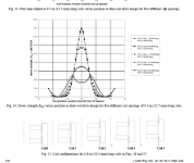
First, I experimented with the coils, and found out that using 3 or 5 coils with different densities results in a more linear BL:
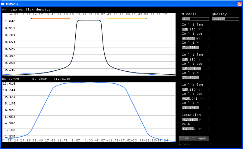

This is a kind of LMT winding but the results are not perfect.
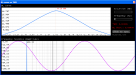
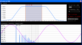
Therefore I did a third app i wanted to show. I was thinking about gradually-wound coils for a while so i did an application that calculates such a gradually-wound coil. There are more turns at the ends of the coil, and fewer at the inside:

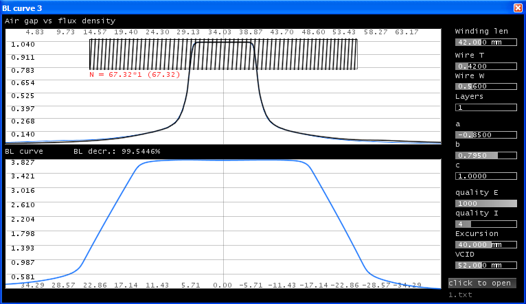
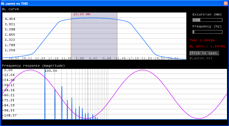
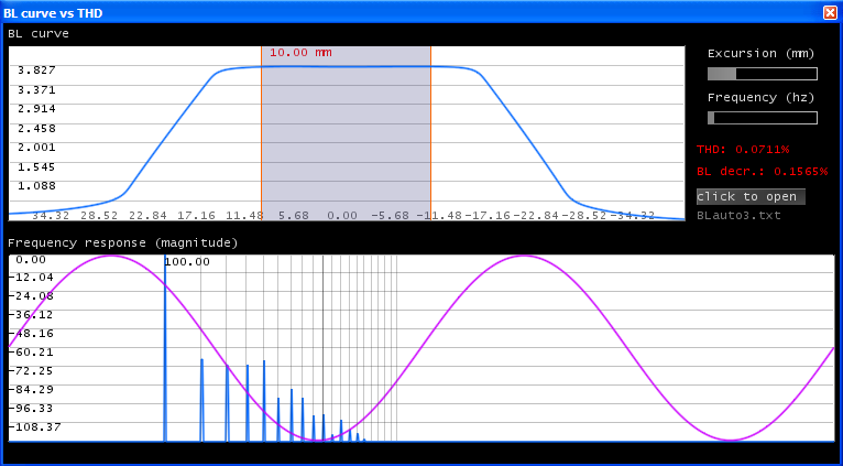
The BL curve is excellent! Parabolic curves are used to approximate the linear BL figure. The distortion figures are also shown. Furthermore, the winding data is calculated in a txt file too. It's a good question whether such a professional winding machine exist, but it's worth to try it.
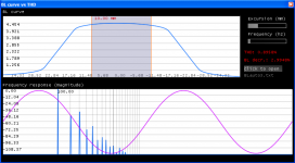
Here is a strong opposite winding just to show how it looks like: (There are more turns at the center)

I hope this was useful.
Regards,
Akos
These must have been the Mkii series, AFAIK the original had ceramic magnets.
Anyway, i just wanted to tell my conclusions, it might be useful to beginner DIYers who are interested in basic motor structures.
First, here is the app:
app.zip
Anyone reading please use it carefully, as it is beta.
Furthermore, I wanted to say a few words about my actual ideas of better BL curves.
First, I experimented with the coils, and found out that using 3 or 5 coils with different densities results in a more linear BL:
This is a kind of LMT winding but the results are not perfect.
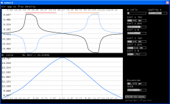
Therefore I did a third app i wanted to show. I was thinking about gradually-wound coils for a while so i did an application that calculates such a gradually-wound coil. There are more turns at the ends of the coil, and fewer at the inside:
The BL curve is excellent! Parabolic curves are used to approximate the linear BL figure. The distortion figures are also shown. Furthermore, the winding data is calculated in a txt file too. It's a good question whether such a professional winding machine exist, but it's worth to try it.
Here is a strong opposite winding just to show how it looks like: (There are more turns at the center)
I hope this was useful.
Regards,
Akos
Attachments

Well, I admit. Don't know how motional feedback works. Maybe it's beyond comparable.
But is that feedback sensor realizable for diyers?
I'd say it is only realizable by DIYers because it is tricky to set up commercially.
First, you don't need me to point out the historic direction of sound reproduction development in the last 80 years has been through better feedback systems, with loudspeakers the final frontier.
Several methods to collect a feedback signal but in my opinion driver voice coil methods are best. Not the only way to query a voice coil, but I think a custom winding is best way... not that I have any idea what that winding should be like (most likely many turns of light wire). For sure, with a superior driver magnet conception, even more appealing to use a voice coil feedback method.
So even if you aren't thinking of motional feedback, I urge you to have a spare winding so you can "watch" your driver (which I'd also say to anybody else with a two-winding former). That signal can be examined in ways never possible with messy acoustic signals bouncing around a room (which is a reason VC feedback works better than mic feedback).
Ben
Last edited:
Since 1956. Well, I wish health and happiness to you and yours, I suppose.
- Status
- This old topic is closed. If you want to reopen this topic, contact a moderator using the "Report Post" button.
- Home
- Loudspeakers
- Subwoofers
- BL distortion prediction / analysis in subs