Can anyone figure out what's going on in the Danley CS-30? I can't figure out how they're getting a bandpass-ish response curve along with an impedance curve that almost looks like a sealed box.
Based on some comments from Ivan Beaver, it looks like the CS-30 complements the TH-Mini well, so I thought I'd pit them head-to-head.
(According to Beaver, the CS-30 digs deeper at the cost of low frequency efficiency, but the Mini has higher efficiency *and* higher power handling than the TH-Mini in the octave from 40 to 80hz.)
Comments here:
zmarchive.com psw-srf: 35103 Mini Subs
Here's the specs.
- Name : TH-Mini / CS-30
- Weight : 76lbs / 83lbs
- Driver : 12" / 12"
- Dimensions (in) : 24 x 15 x 22.5 / same
- External Volume (cubic feet) : 4.69 / same
- Internal Volume (cubic feet, estimated) : 3.5cf / same
- power handling (watts) : 700 continuous, 1400 program / 400 continuous, 800 program
- Sensitivity : 101dB / 95dB
Having worked with the TH-mini, I can say that it really doesn't put out below 50. That being said, it hits 128dBspl solid for hours on end. I had one running in-doors for 5 hours, I had to leave for most of it. When I came back there was about 150 people in the room enjoying the music, the amp was clipping and the DJ mixer clipping(digital...sigh) and the smell of hot voice coil was immediately apparent. That was some seriously low crest factor content and the TH-mini kept playing. For my uses the TH-mini doesn't go low enough but for many small live shows, you'd be hard pressed to find and easier to use more reliable speaker.
Patrick...I know what you are thinking...no you can't fit 4 of them in your car...lol =D
The CS-30 seems to fit the same driver physical limitations as the TH-mini. If you double the power to a cs-30 it's spl would match the mini. The difference in response on the higher end I think is due to the port acting like a short circuit. In the low end the port radiation is less than 90deg out of phase from the woofer so you get coupling. This type of response is usually from a slightly over sized enclosure but the internal volume matches an idealized sim of the lab 12. I think they use a version with a 3" vc though.
Perhaps it's possible that that cone has mass added to it, but probably not.
I do know that danley is unique in their rating method as their program power rating is based on the point where THD exceeds a specific level. That may account for the difference in power ratings. I think this is a case of a very similar driver optimized for two very different sub applications.
As for the impedance curve... it looks like the result of port compression but how could that be?
Danley has run both of them crossedover as a dual band sub system and it was pretty flat from just under 30 to above 200 and a VERY nice phase plot with less than 180deg unwrapped shift across that band.
In conclusion...I'm tired and that probably didn't make much sense.
Happy day after the end of the world =)
-Matt
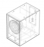
What do u mean? There's a wireframe drawing of the internals. You know the external dimms, and can take a guess on a suitable driver for it. The port wall seems to taper, then flare back up towards the front of the cabinet.
Look at the impedance curve and phase curve. It looks likes a sealed box.
If I had to guess, I'd venture that there are two tunings, causing the expected dip in the impedance curve that's spread out by the multiple tunings.
But that's just an educated guess.
vent of the cs 30
It is vented speaker.The vent of the cs 30 has not the same cross section over it's entire lenght. At both ends its aprox the double of in the middle. I think it is something like the vented sub of the hla series of jbl HLA Series
Even Bose used something similar for the vents of their 502b sub.
I think the falling response above 70 Hz is the nature of the used speaker ( a modified lab12 with added mass??).
I have owned 2 TH-mini's and they are tapped horns with a b&c 12" speaker
Look at the impedance curve and phase curve. It looks likes a sealed box.
If I had to guess, I'd venture that there are two tunings, causing the expected dip in the impedance curve that's spread out by the multiple tunings.
But that's just an educated guess.
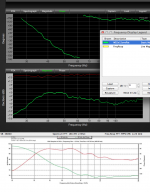
Looking at the cabinet design, it is obviously a single ported cabinet. The port design has been described in JBL white papers, it reduces turbulence at high port velocity.
As far as the impedance response, it does look odd for a cabinet that is ported.
As you can see in the comparison of a Lab 12 in an oversized (underdamped) box and the CS-30 below, the Lab 12 Fb is higher, but they both have very similar phase and magnitude response above Fb.
Art
Attachments
It is vented speaker.The vent of the cs 30 has not the same cross section over it's entire lenght. At both ends its aprox the double of in the middle. I think it is something like the vented sub of the hla series of jbl HLA Series
Even Bose used something similar for the vents of their 502b sub.
I think the falling response above 70 Hz is the nature of the used speaker ( a modified lab12 with added mass??).
I have owned 2 TH-mini's and they are tapped horns with a b&c 12" speaker
I think I figured it out
")
Keep in mind, I was completely wrong about how the tapped horn worked when it first came out half a decade ago, so bear with me...
But here's what I think is going on in the CS-30:
- The CS-30 *is* something like a vented box, but with a twist
- In a 'typical' vented box, the port is tuned to a frequency that's equal to or below the FS of the driver. For instance, a QB3 box for the LAB12 is 4.1 cubic feet, with an FB and an F3 of 22hz.
- If you reduce the box size, the vented peak becomes both louder and higher in frequency. You get 'one note bass.'
- The unusual twist in the CS-30 is that the vent has a reverse taper. My hypothesis is that the reverse taper of the vent makes it a bit resistive, and perhaps reduces the level of the helmholtz peak
As I see it, the coolest thing about the 'invisible bandpass' is that it allows you to use a woofer that's too big for the box. For the last few years I've been building a lot of tapped horns with small woofers, but I've slowly started to realize that there are a lot of advantages to big woofers in small boxes, since maximum output is generally dictated by displacement at low frequencies. (IE, in a horn or tapped horn, the gain is achieved *above* the tuning frequency; so the horn does nothing to improve output below tuning. Therefore, displacement is very important at low frequency.)
I'll post some sims shortly, which will explain my hypothesis better.
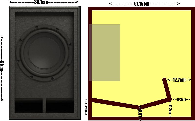
I took the images available online and 'reverse engineered' the box. This is what I came up with.
The image is a bit small, but the important dimensions are in the port. Here are the details:
- The end of the port terminates in a slot vent that's 7.62cm tall by 34.29cm wide.
- The vent narrows to a dimensions that's 3.8cm tall. That segment of the vent is 25.9cm long.
- The vent then begins to widen as we go towards the lower right corner of the sub. That segment of the vent is 17.27cm long. At the lower right corner of the sub box the vent height is 10.2cm.
- The final segment of the vent is 10.2cm long. The vent height at the final segment is 12.7cm. Note that the vent turns 90 degrees.
I'll be looking forward to your sims:^).I think I figured it out
[*]In a 'typical' vented box, the port is tuned to a frequency that's equal to or below the FS of the driver. For instance, a QB3 box for the LAB12 is 4.1 cubic feet, with an FB and an F3 of 22hz.
[*]If you reduce the box size, the vented peak becomes both louder and higher in frequency. You get 'one note bass.'
I'll post some sims shortly, which will explain my hypothesis better.
When box size is reduced, and Fb is kept the same, the vented peak reduces.
The Smaart comparison I posted was a single Lab 12 in this dual design:
FREE SUB PLAN: Dual Lab12 (Front Loaded) by Welter Systems
The "too big" box results in nearly the same LF port output, with a falling upper response, very similar to the DSL CS-30.
The single Lab 12 is 5 dB more "sensitive" than the dual in the 40-50 Hz range.
Art
The 90 degree "turn" makes the vent air velocity more symmetrical in both directions, the inside is more similar to the outside than if it ended before the turn.I took the images available online and 'reverse engineered' the box. This is what I came up with.
The image is a bit small, but the important dimensions are in the port. Here are the details:
[*]The final segment of the vent is 10.2cm long. The vent height at the final segment is 12.7cm. Note that the vent turns 90 degrees.
[/list]
You will be surprised to find in the real world (not in your sim) that the 90 degree wide turn adds little to the port length.
Have fun with your sims!
Art
I'll be looking forward to your sims:^).
When box size is reduced, and Fb is kept the same, the vented peak reduces.
The Smaart comparison I posted was a single Lab 12 in this dual design:
FREE SUB PLAN: Dual Lab12 (Front Loaded) by Welter Systems
The "too big" box results in nearly the same LF port output, with a falling upper response, very similar to the DSL CS-30.
The single Lab 12 is 5 dB more "sensitive" than the dual in the 40-50 Hz range.
Art
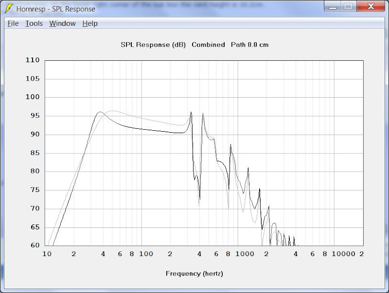
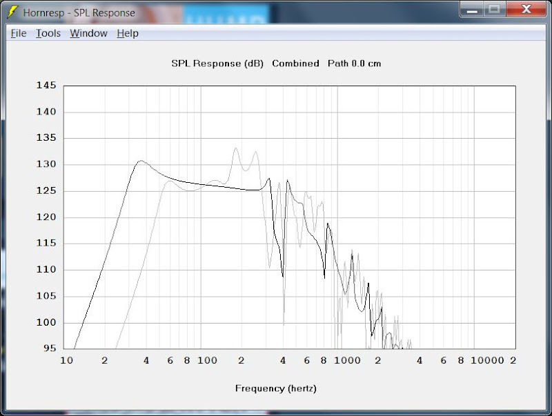
Here's a hornresp sim of my 'guesstimate' of what the CS-30 is. The black line is with one woofer. The grey line is with two woofers, minus 3dB.*
In the sim, I'm seeing that output at resonance is basically determined by the dimensions of the vent. This makes sense, as the woofer cones are barely moving, so output is largely determine by the size of the vent, it's efficiency, and how much power is going into the woofer voice coils.
Once we're about half an octave above the tuning frequency, we see that the output of the vent is adding less and less, so the response shape is largely dictated by the woofer. (IE, the second woofer adds about 3dB more output.)
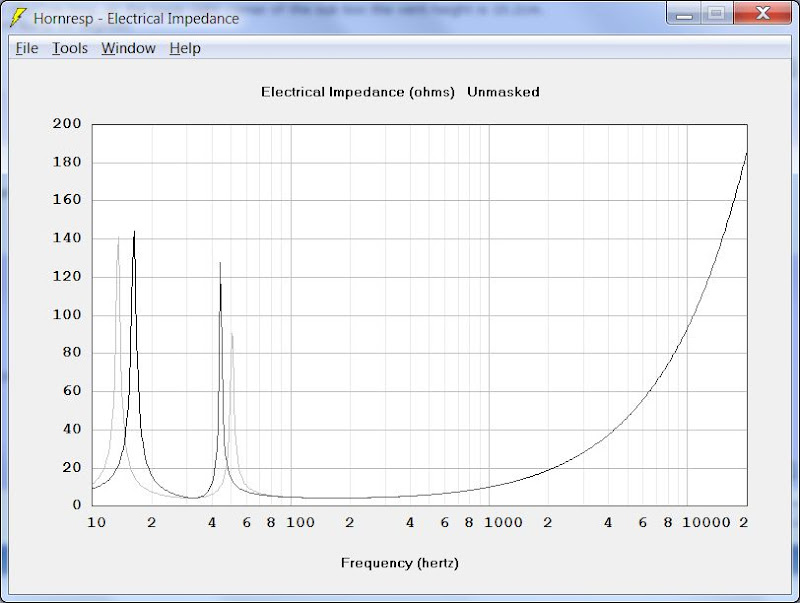
Here's the impedance curve. It looks like we *do* have the classic twin impedance peaks of a vented box. The reason we don't see them in the DSL graph is that the graph is cut off at 20hz.

Here's the phase response of the two vented boxes. Looks fairly close to the DSL graph.
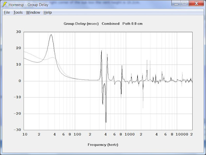
The group delay curve of the box with one woofer is quite a bit worse than with two.
I'm a bit of a noob when it comes to group delay. If I understand it correctly (and I probably don't), the reason that the single woofer box has higher group delay is that the peak in the single woofer box is narrower. (IE, the closer you can get to a 'flat line' in the SPL graph, with flat phase, the closer you'll get to flat group delay curve.)


It's interesting that Ivan Beaver recommended the use of the CS-30 *and* the TH-Mini. I'm guessing that it's a bit of a yin-yang thing, basically the CS-30 has a big bump in output right where the TH-Mini needs it, around 35hz. So the CS-30 almost acts like a bandpass subwoofer, augmenting the low-end of the CS-30, while also buying a bit more efficiency where the CS-30 is acting like a direct radiator (above 50hz or so.)
* if anyone is curious how I modeled these, I'll explain how in the next post
Last edited:
In my last post, I mentioned that I'd explain how I simmed these with hornresp. Here's how:
1) AFAIK, hornresp can't model vented boxes where the port isn't a constant cross section.
2) In order to model these, I basically turned the model inside out.
It's the same method that I use to model back loaded horns in hornresp. You set the volume of the rear chamber "VRC" to zero. Under the 'tools' menu, you set the chamber to 'rear lined'. (Which doesn't do anything, since it's zero, but it eliminates the throat adaptor.) The volume of the throat chamber becomes the volume of the vented box. In the pic above, you can see how it's similar to the CS-30; there's a coupling chamber on one side of the woofer.
3) When doing your sims, be sure to select 'combined response' from the menu 'tools'. If you don't do that, all you'll see is the output of the port alone.
In order to compare the output of one woofer versus two, in the same box, here's what I did:
1) Model the first box
2) Copy that box to a second entry in Hornresp
3) Double the volume of everything in the second box. (Double the area of the horn segments, double the volume of the throat chamber, etc.)
4) Under the 'tools' menu, model the second sub box with two drivers in parallel, and two in series
5) Set the voltage on the second box to 2.0 volts, and the voltage on the first box to 2.83
I know that some might argue that you could get the same results by simply creating a second box, and dropping the voltage from 2.0 to 2.83V. But that only holds true for the SPL graph; the impedance graphs will be skewed by the parallel wiring. Which is why I do a series-parallel wiring scheme, with twice the box volume. Makes for an 'apples to apples' comparison of the most important graphs. (phase, spl, impedance, group delay.)
1) AFAIK, hornresp can't model vented boxes where the port isn't a constant cross section.
2) In order to model these, I basically turned the model inside out.
An externally hosted image should be here but it was not working when we last tested it.
It's the same method that I use to model back loaded horns in hornresp. You set the volume of the rear chamber "VRC" to zero. Under the 'tools' menu, you set the chamber to 'rear lined'. (Which doesn't do anything, since it's zero, but it eliminates the throat adaptor.) The volume of the throat chamber becomes the volume of the vented box. In the pic above, you can see how it's similar to the CS-30; there's a coupling chamber on one side of the woofer.
3) When doing your sims, be sure to select 'combined response' from the menu 'tools'. If you don't do that, all you'll see is the output of the port alone.
In order to compare the output of one woofer versus two, in the same box, here's what I did:
1) Model the first box
2) Copy that box to a second entry in Hornresp
3) Double the volume of everything in the second box. (Double the area of the horn segments, double the volume of the throat chamber, etc.)
4) Under the 'tools' menu, model the second sub box with two drivers in parallel, and two in series
5) Set the voltage on the second box to 2.0 volts, and the voltage on the first box to 2.83
I know that some might argue that you could get the same results by simply creating a second box, and dropping the voltage from 2.0 to 2.83V. But that only holds true for the SPL graph; the impedance graphs will be skewed by the parallel wiring. Which is why I do a series-parallel wiring scheme, with twice the box volume. Makes for an 'apples to apples' comparison of the most important graphs. (phase, spl, impedance, group delay.)
An externally hosted image should be here but it was not working when we last tested it.

Definite a yin-yang thing with these two subs. In the sims above, I've simulated a pair of CS-30s* and a single TH-Mini. It's really interesting that the Mini is struggling right where the CS-30 has displacement to burn, and vice versa. (See how the xmax peaks and dips complement each other?)
I think this is really clever. There's no reason that our subs need to match, in fact there are a lot of good reasons to have asymmetrical subs:
1) the last thing you want with your subs is to have them all run out of output at the same time
2) Vented boxes and tapped horns 'ring' due to delay; so asymmetrical impedance curves might prevent a situation where all the subs are hitting a note that's particularly obnoxious. You might notice this with a single vented sub, where certain notes can sound really obnoxious
3) Combining vented subs with tapped horns gives you the small footprint of vented boxes for ULF along with the high efficiency of tapped horns
4) Multiple subs smooth out room peaks, a la Geddes
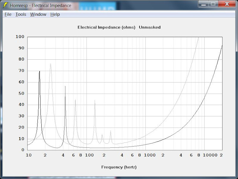
Here's the impedance curve. We see the same thing in the impedance curve that we see with the displacement curve; basically the dips in one sub complement the peaks in the other. I wonder if this might make it possible to run multiple subs in parallel? Someone who understands impedance phase would be better suited to answer this than me
And here's the SPL curve, with 400 watts going into each of three subs. What a gorgeous curve! The two complement each other so well. The CS-30 extends the low frequency output of the TH-Mini, while the mini belts out the SPL above 50hz.
Note that the three subs combined may generate as much as 130dB in the three octaves from 32.5hz to 250hz. Total overkill for most homes, but would be a heck of a setup for a bar or club. And all in three boxes that weigh less than 100lbs each! In a pinch you could almost cram this into a Volkswagen Golf. (My TH-Mini clone fits just fine on the back seat of my Accord.)
WOW.
Fb is determined by the length and area of a vent.Here's a hornresp sim of my 'guesstimate' of what the CS-30 is. The black line is with one woofer. The grey line is with two woofers, minus 3dB.*
In the sim, I'm seeing that output at resonance is basically determined by the dimensions of the vent. This makes sense, as the woofer cones are barely moving, so output is largely determine by the size of the vent, it's efficiency, and how much power is going into the woofer voice coils.
* if anyone is curious how I modeled these, I'll explain how in the next post
Low level output is largely independent of vent size, though at high drive levels, a small vent is not adequate. Hornresp does show port velocity, one can estimate whether the vent is large enough by velocity.
The CS 30 looks like a Lab 12, has the power rating of a Lab 12, but could be a variant with different TS parameters.
Your simulation shows less of a low peak than the DSL charts, only 5 instead of 10 dB, while Hornresp usually exaggerates them.
I'm curious as to why you would use 2 volts and 2.83 volts on a speaker with a claimed minimum impedance of 6.5 ohms (though the CS 30 chart looks like the minimum is around 2 ohms at 20 Hz), and what you used for speaker parameters.
The Lab 12 has an impedance minimum of about 4.29 ohms, the Lab 12C (which looks the same) 3.11.
Art
Patrick, take a look at the relative phase of the outputs of the CS-30 and TH-mini when used together. Trap for young players... hint: think about what happens to the phase of the output of a vented speaker below resonance.
Regarding your comments about the interleaved impedance peaks, look at Horst Moller's work with his "doppelhorns".
Regarding your comments about the interleaved impedance peaks, look at Horst Moller's work with his "doppelhorns".
Hi Patrick Bateman,
This thread may be of interest to you: http://www.diyaudio.com/forums/subw...kabak-modeling-bassreflex-qb5-alignments.html
Regards,
This thread may be of interest to you: http://www.diyaudio.com/forums/subw...kabak-modeling-bassreflex-qb5-alignments.html
Regards,
Very interesting stuff. My 15" dayton ho box has very similar dimensions and response curve to the cs30, with slightly low extension, possibly more output and power handing. I had not thought about using a complex port shape.
http://www.diyaudio.com/forums/subwoofers/219923-ultra-compact-ported-15-dayton-ref-ho.html
http://www.diyaudio.com/forums/subwoofers/219923-ultra-compact-ported-15-dayton-ref-ho.html
Fb is determined by the length and area of a vent.
Low level output is largely independent of vent size, though at high drive levels, a small vent is not adequate. Hornresp does show port velocity, one can estimate whether the vent is large enough by velocity.
The CS 30 looks like a Lab 12, has the power rating of a Lab 12, but could be a variant with different TS parameters.
Your simulation shows less of a low peak than the DSL charts, only 5 instead of 10 dB, while Hornresp usually exaggerates them.
I'm curious as to why you would use 2 volts and 2.83 volts on a speaker with a claimed minimum impedance of 6.5 ohms (though the CS 30 chart looks like the minimum is around 2 ohms at 20 Hz), and what you used for speaker parameters.
The Lab 12 has an impedance minimum of about 4.29 ohms, the Lab 12C (which looks the same) 3.11.
Art
It's funny, for the longest time I've operated on the assumption that big vents were more efficient than small vents. For instance, I'd always believed that a 20cm vent would produce more SPL than a 10cm vent, due to the increase in vent area.
But I ran some sims, and you have proved me wrong. Based on the sims, a small vent is just as efficient as a big vent.
Now I know there are some factors that hornresp can't compensate for:
1) turbulence in the port
2) compression in the port
Admittedly, these are actually less of a factor in a design like the CS-30, where there's a high tuning. (Since port compression becomes a bigger problem at lower frequencies.)
I would post some pics of the simulations of an 8" port and a 4" port, but they're practically the same picture. Much to my surprise, a larger vent doesn't increase SPL. (At least as far as Hornresp is concerned, see the caveats above.)
- Status
- This old topic is closed. If you want to reopen this topic, contact a moderator using the "Report Post" button.
- Home
- Loudspeakers
- Subwoofers
- Featherweight Title Fight