I'd like to post a series of threads about a project I'm going public with: the "Eburon". The eventual design will be a full-ranger in a QB5 alignment, with a cabineth optimized to reduce reflections/diffraction on both sides of the cone. This will be the 5.1 sattelite speaker to go with the bDEAP sub I already have.
The reason I post this in the subwoofer forum, is because I want to split up the design steps, and the first steps are beneficial for subwoofer designers. For the latter I'll go to the other appropriate forums. To the mods: feel free to move this thread to a more suitable place if you deem it nessesairly.
Ideally I can get some gears turning with the brighter minds and more Akabak experienced members across the DIYaudio forum, so the community can benefit from the condensed knowledge here. There have been some instances recently of people asking about support for some of the things I'll want to tacle in this endeavor, so this way they'll find the knowledge to do so without futilessly nudging the program developers for support of filters in their programs.")
- Modeling a bassreflex enclosure with internal reflections in Akabak
- Calculating and then modeling a QB5 Class II enclosure with passive HP filter in Akabak.
- Model and assess baffle step/diffraction
- Model resonators to absorb peaks/reflections in the backwave.
In the next few days I'll try to type out the first step and post it here in this thread. Hopefully I'll get some feedback and this whole thing gets rolling. (And also it's a good motivator to get down and do some things to post the results instead of keep pushing it before me!)
The reason I post this in the subwoofer forum, is because I want to split up the design steps, and the first steps are beneficial for subwoofer designers. For the latter I'll go to the other appropriate forums. To the mods: feel free to move this thread to a more suitable place if you deem it nessesairly.
Ideally I can get some gears turning with the brighter minds and more Akabak experienced members across the DIYaudio forum, so the community can benefit from the condensed knowledge here. There have been some instances recently of people asking about support for some of the things I'll want to tacle in this endeavor, so this way they'll find the knowledge to do so without futilessly nudging the program developers for support of filters in their programs.
- Modeling a bassreflex enclosure with internal reflections in Akabak
- Calculating and then modeling a QB5 Class II enclosure with passive HP filter in Akabak.
- Model and assess baffle step/diffraction
- Model resonators to absorb peaks/reflections in the backwave.
In the next few days I'll try to type out the first step and post it here in this thread. Hopefully I'll get some feedback and this whole thing gets rolling. (And also it's a good motivator to get down and do some things to post the results instead of keep pushing it before me!)
Base model
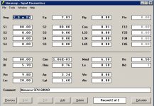
OK, lets see. The driver I choose is the Monacor SPH-68XAD (I've used its -60X cousin in the past and I liked it.)
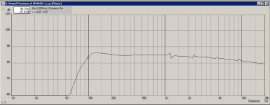
Once put in a 9,8L box with a 18x18mm square vent of 16mm long, the (flat) F3 is 60Hz. With a little over 1mm xmax, it barely holds itself at 2 watts input. In this configuration, a friend of mine still uses them for the last years next to his plasma screen, without the need for a sub.
And judging from the SPL, above 2 watts...
This can all be modeled in HornResp and then be exported to AkAbak. (Just make sure you get the T/S parameters right, or Mr. McBean makes you feel like a fool. )
You can use an "Enclosure" element in your script, but if you use a "Duct" element, you can input the width, height and depth of a rectangular box and you have the Viscosity parameter to play with to simulate stuffing. The internal reflections/resonances of the backwave, will also be visible in the plot.
Here is the script: (I have to admit, once I cleaned everything up to this simple script, the SPL plot smoothed out a lot, but the basic resonances are there. Increase the viscosity parameter to 4 to see the effect of stuffing.)
|DATA EXPORTED FROM HORNRESP - RESONANCES NOT MASKED
|COMMENT: Monacor SPH-68XAD
|~~~~~~~~~~~~~~~~~~~~~~~~~~~~~~~~~~~~~~~~~~~~~~~~~~~~~~~~~
|REQUIRED AKABAK SETTINGS:
|File > Preferences > Physical system constants:
|Sound velocity c = 344m/s
|Medium density rho = 1.205kg/m3
|Sum > Acoustic power:
|Frequency range = 10Hz to 20kHz
|Points = 533
|Input voltage = 2.83V rms
|Integration = 2Pi-sr
|Integration steps = 1 degree ... 1 degree
|Integration method = Cross
|~~~~~~~~~~~~~~~~~~~~~~~~~~~~~~~~~~~~~~~~~~~~~~~~~~~~~~~~
Def_Driver 'Driver'
Sd=80.00cm2
Bl=5.70Tm
Cms=1.10E-03m/N
Rms=0.756Ns/m
fs=60Hz
Le=0.50mH
Re=6.50ohm
System 'System'
Driver Def='Driver''Driver'
Node=1=0=100=101
Duct 'Rear chamber'
Node=200=100
WD=0,20m
HD=0,33m
Len=0,148m
Visc=0
Radiator 'Front Driver'
Node=101
SD=80.00cm2
Duct 'Bassport'
Node=200=102
WD=0,018m
HD=0,018m
Len=0,016m
Visc=0
Radiator 'Bassport Exit'
Node=102
SD=3.24cm2
OK, lets see. The driver I choose is the Monacor SPH-68XAD (I've used its -60X cousin in the past and I liked it.)
Once put in a 9,8L box with a 18x18mm square vent of 16mm long, the (flat) F3 is 60Hz. With a little over 1mm xmax, it barely holds itself at 2 watts input. In this configuration, a friend of mine still uses them for the last years next to his plasma screen, without the need for a sub.
And judging from the SPL, above 2 watts...
This can all be modeled in HornResp and then be exported to AkAbak. (Just make sure you get the T/S parameters right, or Mr. McBean makes you feel like a fool.
)You can use an "Enclosure" element in your script, but if you use a "Duct" element, you can input the width, height and depth of a rectangular box and you have the Viscosity parameter to play with to simulate stuffing. The internal reflections/resonances of the backwave, will also be visible in the plot.
Here is the script: (I have to admit, once I cleaned everything up to this simple script, the SPL plot smoothed out a lot, but the basic resonances are there. Increase the viscosity parameter to 4 to see the effect of stuffing.)
|DATA EXPORTED FROM HORNRESP - RESONANCES NOT MASKED
|COMMENT: Monacor SPH-68XAD
|~~~~~~~~~~~~~~~~~~~~~~~~~~~~~~~~~~~~~~~~~~~~~~~~~~~~~~~~~
|REQUIRED AKABAK SETTINGS:
|File > Preferences > Physical system constants:
|Sound velocity c = 344m/s
|Medium density rho = 1.205kg/m3
|Sum > Acoustic power:
|Frequency range = 10Hz to 20kHz
|Points = 533
|Input voltage = 2.83V rms
|Integration = 2Pi-sr
|Integration steps = 1 degree ... 1 degree
|Integration method = Cross
|~~~~~~~~~~~~~~~~~~~~~~~~~~~~~~~~~~~~~~~~~~~~~~~~~~~~~~~~
Def_Driver 'Driver'
Sd=80.00cm2
Bl=5.70Tm
Cms=1.10E-03m/N
Rms=0.756Ns/m
fs=60Hz
Le=0.50mH
Re=6.50ohm
System 'System'
Driver Def='Driver''Driver'
Node=1=0=100=101
Duct 'Rear chamber'
Node=200=100
WD=0,20m
HD=0,33m
Len=0,148m
Visc=0
Radiator 'Front Driver'
Node=101
SD=80.00cm2
Duct 'Bassport'
Node=200=102
WD=0,018m
HD=0,018m
Len=0,016m
Visc=0
Radiator 'Bassport Exit'
Node=102
SD=3.24cm2
Last edited:
Hi Cordraconis,
I'm going to be watching your project "Eburon" with high interest. I think it would be great, if the parts could stay consolidated in one thread.
When messin' around with compound arrangements in Hornresp I split out the bass reflex portion, and it transferred just fine into AkAbak. Naturally, this does not give you a rectangular box, or duct, and no stuffing, but the basic method seems to work.
I renamed the file extension from .aks to .txt - to use it just rename it back to .aks.
Regards,
Attachments
Last edited:
This can all be modeled in HornResp and then be exported to AkAbak. (Just make sure you get the T/S parameters right, or Mr. McBean makes you feel like a fool. )
You can use an "Enclosure" element in your script, but if you use a "Duct" element, you can input the width, height and depth of a rectangular box and you have the Viscosity parameter to play with to simulate stuffing. The internal reflections/resonances of the backwave, will also be visible in the plot.
Hi Cordraconis
A screenshot of the Hornresp input parameters used to create the Akabak script would be very useful at this stage.
Regards Xoc1
Should be done.Hi Cordraconis
A screenshot of the Hornresp input parameters used to create the Akabak script would be very useful at this stage.
Regards Xoc1
(Don't forget to choose HornResp "Combined output" option for the correct SPL plot.)
I've already modified/detailed the script above, but this should get you started.
Also I think the internal reflections are dependant on the position where the driver loads the cabinet, but that will be determined when I tacle the diffraction properties of the front baffle. I'm not sure if AkAbak has a way of inputting those point-of-loading information into a "Duct" Element. But that's for later. Next up is how to use the QB5 tables to bump-tune the cabineth.
Also, please keep in mind I'm not making this as a tutorial, more like a method for myself and hopefully when I make a mistake someone can step in and correct me. Eventually this wil benefit everyone.
As I have no woodworking capabilities nor space in my small house, I'll have a carpenter or woodworker make the cabinets, once the final design is finished.
Attachments
Further to what I said above, Akabak does not, by default, model resonances in ducts where their areas change suddenly. So in the above model, Akabak will not model the reflections from the change in area where the "enclosure" duct joins the "port" duct. You need to add acoustic mass and resistance at the join. I suggest using an Enclosure rather than a Duct, and use the "Lb" and "Deep/Long" parameters. Also pay attention to the "box loss" parameter Qb/fo. It makes a significant difference to the calculated response. If you want to stuff the enclosure, add an AcouCompliance element.
Further to what I said above, Akabak does not, by default, model resonances in ducts where their areas change suddenly. So in the above model, Akabak will not model the reflections from the change in area where the "enclosure" duct joins the "port" duct. You need to add acoustic mass and resistance at the join. I suggest using an Enclosure rather than a Duct, and use the "Lb" and "Deep/Long" parameters. Also pay attention to the "box loss" parameter Qb/fo. It makes a significant difference to the calculated response. If you want to stuff the enclosure, add an AcouCompliance element.
Thanks for the tips so far!
With regards to your lengthwise-only reflections, I was thinking of using 5 ducts (up, down, left, right and depth) of a correct combined volume, to approximate the internal "eigenmodes". Somewhere in an AkAbak manual they also used multiple Ducts to model a bandpass enclosure, so it should be feasible.
I didn't know the change in area's didn't reflect, aldough I missed them in the SPL plot. Guess I'll hunt for them later and play with the acoustic mass and compliance elements then. Nice tip!
Right now I'm still in a row of working nights (yes, also at X-mas!
 ), but I'll get to my next post soon. Hang on!
Enjoy the hollidays ... if you have them!
Joris
Thanks for the tips so far!
With regards to your lengthwise-only reflections, I was thinking of using 5 ducts (up, down, left, right and depth) of a correct combined volume, to approximate the internal "eigenmodes".
Interesting idea. Remember to leave the far ends of the ducts open circuit to tell AkAbak that the ends of the ducts are closed. I suggest comparing it with a fully specified Enclosure model. I compared your original single-duct model with an equivalent enclosure model and found that they were very similar but the enclosure model better showed the main front-back resonance.
Somewhere in an AkAbak manual they also used multiple Ducts to model a bandpass enclosure, so it should be feasible.
Page 64 of the main manual. Note that the multiple ducts are connected end to end with no changes in area.
I had good food and company today... I also managed to try some AkAbak ideas (see the threads on "Cornu" horns) so it has been a good day all around.
The next step is to modify the "base system" to a QB5 Alignment.
This isn't as straightforward at first glance, since you have to condense out the basics.
First I'll give a brief summary of the Elliot Sound Article about compliance scaling: Loudspeaker Compliance Scaling
When looking at a driver T/S parameters, the Qt factor is not that important. There can be naturally occurring variations till 20% coming from the production line. The article shows some graphs about what happens when the Qt is changed on a given box. Basically there is more ripple in the passband, and when using a filter, there is even less ripple.
Then the article continues with instructions on how to transform the T/S parameters, so the altered parameters can be put into one of the box calc programs which then magically can give the filter assisted response. Winisd is given as an example.
Then some techniques are given on how to modify the amplifier output so the driver behaves as if it would have a different Qt or be differently
filtered.
What I remembered from this, is that if the Qt factor is not THAT important, and even less important when we are using a filtered alignment, the QB5 alignment can be chosen quite straigtforward: Satellites and Subwoofers
Lets look at the QB5 Group II alignment table in the above article. In particular the 3rd column.
I would like to have the -3dB point at 80Hz, and the chosen driver's free air resonance is 60Hz. F3/Fs = 80Hz/60Hz = 1,33. This falls between 2 rows in the table. The first colum gives a desired Qt of a little bit less than 0,4 while the manufacturer states a measured Qt of 0,43 - about 10% deviation from the tables. So likely there will be a bit of ripple in the end result, but it should be acceptable.
Vas/Vb should be around unity, so I'll take Vas = Vb = 9,7L box volume.
Fb/Fs = x Hz/60Hz = 1,28 so the box should be tuned to 77Hz.
Fa/Fs = x Hz/60Hz = 1,34 so the filter should be at 80Hz. With 1/Qa = 1,59 (the inverse of the Q-factor. I'll get back on that later.)
All this information can be fed into Eminence Designer/BassBox pro - which has recently been mentioned a few times on this forum - or in Akabak which can also model active filters. By juggling around the port tuning frequencies, box sizes or active filter tuning frequencies, one can reach the desired F3 frequency in a few steps.
However, since I wanted to make a self-contained system, I opted for a passive filter inside the cabinet. This has the problem that one needs a way of designing a passive filter with a variable Q-factor. I couldn't find such a way at first, and I tried to contact the author and also website owner of the QB5align article for help, but to no avail. Maybe my question was foolish, got lost in the heap or simply not enough time for it. As the saying here in Belgium goes: "A 'No' you have for sure, a 'yes' you can get." Meaning it never hurts to try.
If any of the author(s) or someone more knowledgeable than me happens to pass by this thread, please feel free to share any knowledge or insights you have.
I got my insight when I looked at paragraph 5.0 (or more correctly: the lines above paragraph 6.0) of the article on passive crossovers: Passive Crossover Network Design
There we see the full original formulae for finding the capacitor and inductor values of 2nd order passive filters, along with a short overview of ... the different 1/Q factors (=d factor) needed to get Linkwitz-Reiley, Bessel, etc... filters. When I saw 1/Q mentioned, I knew I had found what I was looking for!
Edit: Hmmmm... With what I have explained so far, one can try to model the passive highpass-filter himself. (Just don't forget to adjust the entrance nodes of the driver accordingly, like this:
Driver Def='Driver''Driver'
Node=2=0=100=101
Capacitor | In Series with driver
Node=1=2
C=139uF
Coil | In Parallell with driver
Node=2=0
L=28,5mH
Rs=1ohm
HOWEVER... In Eminence Designer/BassBox, a single 800µF capacitor (=1st order filter) in series seemed to give a flat SPL response, with the total impendance of the system bottoming around 1,4 Ohms and staying there over a very long freq range (something I don't like to feed to my amplifier.) With the later discovery of the variable Q-formulae and the resulting 2nd-order filter, it nearly doubled till about 2,6 Ohms.
Now, when testing all this in AkAbak, I see none of the above? The driver and box tuning resonances are visible in the impendance plot (they were gone in ED/BB), and the SPL plot also doesn't look like it was before. Hmmm... I'll let it all rest for now and maybe check out SpeakerWorkshop
as I remember it to have a tool to optimize filter component values to a desired SPL curve. Right now I'm thinking about a calculation error, modeling/scripting error in AkAbak, maybe needing a Zobel Network for the box resonance peak, or more generally: severely lacking experience with crossover designing on my part.
Once I've figured out what went wrong (any pointers are welcome!), I'll post the crossover and discuss the power handling and IM distortion benefits of this QB5.
Service message: no more post from me till at least the 2nd of Januari, as my GF feels like a laptop widow right now...
Happy Newyear everyone!
Brian Steele's ported.xls spreadsheet has built-in filter options. It makes modelling QB5 style alignments very easy. www.diysubwoofers.org/design/ported.zip
je m' excuse
I'm terribly sorry for the 3-month wait. I haven't dropped the project, but a serious illment in the family really eats up my weekends. Now recently it looks like I can put some more time into this again.
I haven't sat still either: I have purchased my Onkyo TX-NR818 surround reciever and temporarly put a leftover pair of Akai speakers from the previous house owners on it. I stuffed them with about 80grams of polyfill to tame the boomyness, and the Audissey Room Correction from the amplifier makes it tolerable. (Bass driver is full ranged ??? and there is one cap protecting the 2 inch "tweeter".)
Now on to the passive QB5 crossover:
The passive crossover for a QB5 alignment
-----------------------------------------
With the information above, one modifies the AkAbak script to the correct box volume and port length/area for the chosen QB5 alignment.
In our case this will be 9,7L and a port of 3*3*1,5cm. When modeling the SPL plot, you'll clearly notice the bump around 100Hz.
Next step is to find the impendance at 80Hz *in that box*. Inspect > Network Impendance and clicking on the graph at 80Hz reveals a value of 9
Ohm. This is the R value we must use in the formulae above.
C = 1 / ( 2 * p * Z * d * f ) = 1/ (2 * 3,14159 * 9 Ohm * 1,59 * 80 HZ) = 139 PicoFarad
L = ( Z * d ) / ( 2 * p * f ) = (9 Ohm * 1,59) / (2 * 3,14159 * 80Hz) = 14,31 / 502,65 = 28,5 MilliHenry
When we put this into an AkAbak script, we see that we don't get the expected flat response (like with an active filter.) This is due to the effect of the impendance on the passive components. (There are some good articles about that, and the Elliot Sound Page also has some about countermeasures.)
So what we need is a personalized crossover, dependant on the impendance- and spl-plot. Enter Speaker Workshop, a free program that accepts .frd (=spl plot) and .zma (=impendance plot) files, and has a brute force/Monte Carlo analysis tool to do the tedious work.
To get these files, one could use the export function of Akabak (and modify the data in a spreadsheet) and a tool to generate the phase data column. (Mentioned in "Crossover Simulation in Speaker Workshop - Tutorial",
Speaker Workshop Tutorial )
Alternatively, use HornResp and export the data. Remove the first lines from the file, and you have the needed .FRD and .ZMA files!
Follow the above mentioned tutorial to import the files, choose a standard/stock 2nd order crossover and optimize the 80-2000Hz for maximum flat response. If you get a bump around a certain freq, insert a "Impendance compensation - resonant peak" into the crossover and re-optimize.
This got me a ruler flat response from 80Hz till up. I put the resulting crossover in AkAbak and it looks good, but there are some differences with Speaker Workshop. Maybe someone can shed a light on this. I think AkAbak is more accurate, but with SW one can get about 95% of the way. (Or assume Speaker Workshop is spot-on, and be done with it!)
Anyway, with this I'll conclude the basic QB5 alignment optimization. The whole SW optimization process will have to be re-done once the diffraction, baffle step and internal resonances have been simultated, so no point in taking this further right now.
I'll just stop for a moment on the reduction in excursion by the electrical filter, and other benefits.
In the original unfiltered box, we see a 6dB bump. Once we filter this away, we see the responce is flat, and the excursion is reduced (at 107 Hz) by 25%. Obviously, we can now put in about 4 times more power before we reach xmax, resulting in our original 6dB increase.
Now how about the 25% excursion reduction?
After digging trough the 3-part "Klips Modulation Distortion" article, we can conclude that the reduction in Modulation distortion is lineair with excursion, resulting in a 25% decrease! This is beyond my wildest imagination. Surely a fullranger has its own issues, but once my whole analysis is done, I am truly confident I'll get the best possible response from it.
Sorry again for the very long wait, but I'll do my best.
Next up: internal reflections!
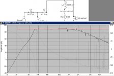
Here is the AkAbak script with the SpeakerWorkshop' calculated crossover. Included screenshot is from SW and then from AkAbak.
|~~~~~~~~~~~~~~~~~~~~~~~~~~~~~~~~~~~~~~~~~~~~~
Def_Driver 'Driver'
Sd=80.00cm2
Bl=5.70Tm
Cms=1.10E-03m/N
Rms=0.756Ns/m
fs=60Hz
Le=0.50mH
Re=6.50ohm
System 'System'
Driver Def='Driver''Driver'
Node=3=0=100=101
Capacitor 'C1'
Node=1=2 C=0.141mF
Coil 'L1'
Node=2=0 L=11.38mH Rs=1ohm
Capacitor 'C2'
Node=2=3 C=0.3117mF
Coil 'L2'
Node=3=4 L=10.75mH Rs=5.36ohm
Capacitor 'C3'
Node=4=0 C=0.2496mF
Duct 'Rear chamber'
Node=200=100
WD=0,20m
HD=0,33m
Len=0,147m
Visc=0
Radiator 'Front Driver'
Node=101
SD=80.00cm2
Duct 'Bassport'
Node=200=102
WD=0,030m
HD=0,030m
Len=0,015m
Visc=0
Radiator 'Bassport Exit'
Node=102
SD=9.00cm2
|~~~~~~~~~~~~~~~~~~~~~~~~~~~~~~~~~~~~~~~~~~~~~~
I'm terribly sorry for the 3-month wait. I haven't dropped the project, but a serious illment in the family really eats up my weekends. Now recently it looks like I can put some more time into this again.
I haven't sat still either: I have purchased my Onkyo TX-NR818 surround reciever and temporarly put a leftover pair of Akai speakers from the previous house owners on it. I stuffed them with about 80grams of polyfill to tame the boomyness, and the Audissey Room Correction from the amplifier makes it tolerable. (Bass driver is full ranged ??? and there is one cap protecting the 2 inch "tweeter".)
Now on to the passive QB5 crossover:
The passive crossover for a QB5 alignment
-----------------------------------------
With the information above, one modifies the AkAbak script to the correct box volume and port length/area for the chosen QB5 alignment.
In our case this will be 9,7L and a port of 3*3*1,5cm. When modeling the SPL plot, you'll clearly notice the bump around 100Hz.
Next step is to find the impendance at 80Hz *in that box*. Inspect > Network Impendance and clicking on the graph at 80Hz reveals a value of 9
Ohm. This is the R value we must use in the formulae above.
C = 1 / ( 2 * p * Z * d * f ) = 1/ (2 * 3,14159 * 9 Ohm * 1,59 * 80 HZ) = 139 PicoFarad
L = ( Z * d ) / ( 2 * p * f ) = (9 Ohm * 1,59) / (2 * 3,14159 * 80Hz) = 14,31 / 502,65 = 28,5 MilliHenry
When we put this into an AkAbak script, we see that we don't get the expected flat response (like with an active filter.) This is due to the effect of the impendance on the passive components. (There are some good articles about that, and the Elliot Sound Page also has some about countermeasures.)
So what we need is a personalized crossover, dependant on the impendance- and spl-plot. Enter Speaker Workshop, a free program that accepts .frd (=spl plot) and .zma (=impendance plot) files, and has a brute force/Monte Carlo analysis tool to do the tedious work.
To get these files, one could use the export function of Akabak (and modify the data in a spreadsheet) and a tool to generate the phase data column. (Mentioned in "Crossover Simulation in Speaker Workshop - Tutorial",
Speaker Workshop Tutorial )
Alternatively, use HornResp and export the data. Remove the first lines from the file, and you have the needed .FRD and .ZMA files!
Follow the above mentioned tutorial to import the files, choose a standard/stock 2nd order crossover and optimize the 80-2000Hz for maximum flat response. If you get a bump around a certain freq, insert a "Impendance compensation - resonant peak" into the crossover and re-optimize.
This got me a ruler flat response from 80Hz till up. I put the resulting crossover in AkAbak and it looks good, but there are some differences with Speaker Workshop. Maybe someone can shed a light on this. I think AkAbak is more accurate, but with SW one can get about 95% of the way. (Or assume Speaker Workshop is spot-on, and be done with it!)
Anyway, with this I'll conclude the basic QB5 alignment optimization. The whole SW optimization process will have to be re-done once the diffraction, baffle step and internal resonances have been simultated, so no point in taking this further right now.
I'll just stop for a moment on the reduction in excursion by the electrical filter, and other benefits.
In the original unfiltered box, we see a 6dB bump. Once we filter this away, we see the responce is flat, and the excursion is reduced (at 107 Hz) by 25%. Obviously, we can now put in about 4 times more power before we reach xmax, resulting in our original 6dB increase.
Now how about the 25% excursion reduction?
After digging trough the 3-part "Klips Modulation Distortion" article, we can conclude that the reduction in Modulation distortion is lineair with excursion, resulting in a 25% decrease! This is beyond my wildest imagination. Surely a fullranger has its own issues, but once my whole analysis is done, I am truly confident I'll get the best possible response from it.
Sorry again for the very long wait, but I'll do my best.
Next up: internal reflections!
Here is the AkAbak script with the SpeakerWorkshop' calculated crossover. Included screenshot is from SW and then from AkAbak.
|~~~~~~~~~~~~~~~~~~~~~~~~~~~~~~~~~~~~~~~~~~~~~
Def_Driver 'Driver'
Sd=80.00cm2
Bl=5.70Tm
Cms=1.10E-03m/N
Rms=0.756Ns/m
fs=60Hz
Le=0.50mH
Re=6.50ohm
System 'System'
Driver Def='Driver''Driver'
Node=3=0=100=101
Capacitor 'C1'
Node=1=2 C=0.141mF
Coil 'L1'
Node=2=0 L=11.38mH Rs=1ohm
Capacitor 'C2'
Node=2=3 C=0.3117mF
Coil 'L2'
Node=3=4 L=10.75mH Rs=5.36ohm
Capacitor 'C3'
Node=4=0 C=0.2496mF
Duct 'Rear chamber'
Node=200=100
WD=0,20m
HD=0,33m
Len=0,147m
Visc=0
Radiator 'Front Driver'
Node=101
SD=80.00cm2
Duct 'Bassport'
Node=200=102
WD=0,030m
HD=0,030m
Len=0,015m
Visc=0
Radiator 'Bassport Exit'
Node=102
SD=9.00cm2
|~~~~~~~~~~~~~~~~~~~~~~~~~~~~~~~~~~~~~~~~~~~~~~
Attachments
To sum things up, so that I understand your goal:
You want to take a not so pricey, simple driver like the Monacor and get a QB5 Allignement with a passive Filtering (highpass with a C) inside a ported enclosure. Furthermore then deal with Bafflestep and reduce box-insider Reflexions as much as possible.
As a "bonus" you are looking for a "variable Q" (passive version)..
Correct so far?
Correct, with some nuances.To sum things up, so that I understand your goal:
You want to take a not so pricey, simple driver like the Monacor and get a QB5 Allignement with a passive Filtering (highpass with a C) inside a ported enclosure. Furthermore then deal with Bafflestep and reduce box-insider Reflexions as much as possible.
As a "bonus" you are looking for a "variable Q" (passive version)..
Correct so far?
The fullranger (and the emphasis on internal reflections) is for the merit of imaging for hometheatre. Max SPL will be limited, but the THX reference level is 85dB with 20dB of headroom, which is too loud anyway for a house with neighbours and my girlfriend... Also the sub crossover freq must be 80Hz, so the QB5 is to take the monacor's "extra" below 80Hz and push it up to trade it for about 6dB of extra output, less IM distortion, power compression, etc...
The "variable Q" is to be able to implement the desired Q from the alignment tables into a passive filter, but I think it is not feasable: in the HornResp thread I read that with an active filter there is no back-influence from the driver - easy, but obviously in a passive filter the impendance curve wil effect the Q of the crossover. I guess one should try to separate the desired Q (from the tables) into a sum of the crossover Q and the impendance curve'Q.
So no passive formula for everyone's benefit to make passive QB5's I guess...
Also, baffle step, beaming, back wall reflection... will also effect the unfiltered responce, so I realize now that the crossover will be the last thing to do and that it will be a fit-to-curve reiteration process, rather than a formula-based-nailed-it.
Trying something and realizing it will fail that way (for me) is what I learned with the passive attempt.
Ok, lets clear some stuff up, you have a lot of thoughts here.
Driver choice:
This driver has very low xmax to do bass. Datasheet says 1mm, which is a conservative value, since monacor states the real geometrical xmax with these drivers. so 1,5mm might be realistic, if the driver is symmetrical in its movement (lokking at the age of the driver and the way its constructed - don´t count on it).
So SPLmax will be limited a lot. It doesn´t matter which alignement you chose, as long as its a ported enclosure (with or without a highpass C), max SPL at low frequnzies is always the same with the same driver.
Doing 80Hz with this driver will be very limited and will only work in a very small room if you are stisfied with low levels of volume.
QB5 Alignments are good with drivers having a very high Qts, since these drivers tend not to work in a "normal" ported enclosure, they have very boomy bass. QB5 with a proper C moves everything in place. But again - SPL is still limited, no matter what.
Since your port and the C have a close relationship in how they work together and since the port is always tuned to the same frequency (unless you buy a variable port and change it mechanicaly everytime), chaning C doesnt help a lot without changing the port. The variance of parameters where the values of the tuning and of C "make sense" are in a small range - so the myth of getting whatever response you want by simply changing the Q by changing port an C - has its limits in reality.
A variable C in a passive crossover is exepnsive, intertechnik sells some for speaker development, but doing this with normal capacitors requires buying a lot of them and buliding some kind of matrix switch to change the values...
QB5 Alignements have a high order slope on the lower end and therefore high phase changes. This could get in your way of adding a sub.
The big capacitor for the QB5 Alignemnt does some change to the impedance where baffle-step correction is suited - this has to be taken into account, you are right on this one. Its effect isn´t that great, I´d guess you won´t be needing impedance linearisation here, but to be sure, you´d have to simulate in Akabak to see the results. Of course, bafflestep depends on the size of the enclosure, so you have to think about this one, too.
with back wall reflection I guess you don´t mean whats inside the box but the wall behind the enclosure? How close do you want to get to the wall?
I have some of these drivers here - the wanted quality of a fullrange doing a good job in the mids and with voice is limited with those in my oppinion. Of course, they don´t cost much so its ok for the money you spend. But the lower end will be limited quite alot and midrange will suffer from distortion induced by too much excursion, doppler and intermodulation effects.
I get the impression you want the QB5 Alignement to do some magical trick which gets a lot more out of the speaker then another alignment - this isn't the case.
To calculate a QB5 Alignement, I have a formula somewhere in the drawer which is pretty simple to handle. I could look it up. But it´s designed for very high Qts (0,43 isn´t that high, I am talking about 0,7 and much higher). You will be needing a lot more volume, too than in a normal reflex enclosure.
You should be fine with a normal ported enclosure with this driver.
Last edited:
I already did some comparisons on small commercial sattelites. Some of them claim to go as low as 40Hz, but the sensitivity is then in the low 80's. I feel they swap efficiency for bass extention. Quite the opposite of what I try to do.
Sabbelbacke, Making everything (port and C) variable and adjustable to suit is a very practical approach, which I cannot do, but I guess you have already done that in the past. Cool that you have this facilities.
The living room here is 4x3m (more around 3x3m for practical purposes, hence space is at a premium), so the speakers will be hung on-wall. This will give some boost at the lower frequencies -- "reflector" element in AkAbak to test this --, and having 4 (well 5) speakers is +6dB from the quadruple cone area.
You did make me wonder about two things: How will the room help the speakers, and how much SPL is actually used?
Since I calibrated everything with Audissey, it advised a crossover freq of 40Hz??? I first tought this was an error, but according to their website this can be because of room augmentation. I run it at 80Hz anyway, but I measured the dimentions of my temporarly (AKAI M45-SW) speakers: 10L box and flared port tuned to about 50Hz. A bit on the optimistic side, but it seems in a practical enviroment the calibration microphone does think it is useable to 40Hz. I also think a rapid rolloff or mismatch between sub and sattelite slope will give lobing or diffraction effects, which I think shouldn't be such a problem at those low freq, and if they will, the Adyssey should iron them out. (I'm hoping the amplifier has a "brick wall" crossover so there should be no overlap, but I couldn't get that from the manual.)
SPL-wise I have a simple decibelmeter - my only measuring equipment - and I remembered some volume settings during normal radio listening and some "spirited" action movie scenes. I took my meter at hand and it seems ... 70dB A-weighted and 90dB C-weighted during peak moments are about the loudest I went (so far ;-) Verry reassuring I think.
Tomorrow I don't have to work and I'll try to do some scripting work again.
- Status
- This old topic is closed. If you want to reopen this topic, contact a moderator using the "Report Post" button.
- Home
- Loudspeakers
- Subwoofers
- Project Eburon - Step 1 - Advanced AkAbak modeling of Bassreflex and QB5 Alignments