I'm a little confused on the microphone part though, i thought you would look for a peak (pressure maximum) with the microphone as you are moving it down the pipe ....
I was going by something you said in the THAM15 discussion ...
" The effect would significantly reduce, if not disappear, if I moved the obstruction caused by the cards only a inch or two forwards or backwards in the pipe. I also placed the mic *in* the pipe in that location, and set TrueRTA to Rel mode, the graph started to show a peaked response around the same frequencies that the notch appeared in the tapped-pipe's response curve."
http://www.diyaudio.com/forums/subwoofers/175658-tham15-compact-15-tapped-horn-18.html#post2448729
Yep, it was set in "Rel" mode with the response at the mouth used as the reference. As a result the RTA will show a peak at the dip frequency when the actual response is flat at that frequency, because the RTA is comparing the measured response to the reference.
FWIW, my attempts at DFDing the tapped pipe were not successful. I'm not sure why.
Ok, i think its starting to make sense to me now, 
So Brian, let me make sure i understand this correctly.... The 1/3 in from the mouth point (the same thing as 2/3rds down from the throat) is where you got a dip-free response reading from the microphone correct? It was fairly flat in the midbass .... At that location you saw the best output/pressure at 150hz yet not necessarily a peak compared to the rest of the spectrum but it was a flattish response instead, however its a peak compared to your reference sample which was taken at the mouth right? So we could say that spot is a pressure maximum for 150hz ....
Then that was the same location where you installed the DFD constriction, correct? ....
I wonder why it didn't work for the other box?? Now thats interesting, since the design isn't truly that much different except for the scale of it, a little stuffing , and the lack of taper ...
FWIW, my attempts at DFDing the tapped pipe were not successful. I'm not sure why.
Im curious, was there even much of a dip left to fill in after you added the stuffing to the POC1 tapped pipe? Did you get any sort of effect at all when you tried to add a DFD to it?
I wonder why it didn't work for the other box?? Now thats interesting, since the design isn't truly that much different except for the scale of it, a little stuffing , and the lack of taper ...
Taper makes a difference since it's a 1/2 WL resonator and the pipe is a 1/4 WL: Resonances of open air columns
GM
Ok, i think its starting to make sense to me now,
So Brian, let me make sure i understand this correctly.... The 1/3 in from the mouth point (the same thing as 2/3rds down from the throat) is where you got a dip-free response reading from the microphone correct? It was fairly flat in the midbass .... At that location you saw the best output/pressure at 150hz yet not necessarily a peak compared to the rest of the spectrum but it was a flattish response instead, however its a peak compared to your reference sample which was taken at the mouth right? So we could say that spot is a pressure maximum for 150hz ....
Then that was the same location where you installed the DFD constriction, correct? ....
That's correct.
I wonder why it didn't work for the other box?? Now thats interesting, since the design isn't truly that much different except for the scale of it, a little stuffing , and the lack of taper ...
I'm not sure why. I experimented with it for several hours and couldn't get a result that made any positive difference. Stuffing part of the pipe produced much better audible results.
Im curious, was there even much of a dip left to fill in after you added the stuffing to the POC1 tapped pipe? Did you get any sort of effect at all when you tried to add a DFD to it?
My attempt at DFDing the tapped pipe was done with it unstuffed. Once it's stuffed, a DFD isn't necessary as there's no dip to be concerned about
Awesome! Thank you Brian,
You used poly fiberfill? and you stuffed the first 1/3rd to 1/2 right?
Also, according to the chart in addition to the smoothing effect it looks like you had the side benefit of lowering the fundamental resonance too, maybe 3-5hz ? Good stuff!!
It reminds me of the results that i have seen when stuffing the first half of some Quarter Wave Pipes that I built with a friend ..... We used Polyfill as well ..
Last edited:
Awesome! Thank you Brian,
You used poly fiberfill? and you stuffed the first 1/3rd to 1/2 right?
That's correct.
Thanks for all the kind and inspiring words! But remember that is us who do this together, not just me. Actually it is me who shall say thank you for all your fantastic contribution, both in this thread and in all the others I have read on this forum which are the main source of information that I build my understanding on. I appreciate this philosophy of sharing knowledge and information so much!
Today it is 10 degrees (C) below and my workshop isn’t insulated so no new measurements today.
The other day played with the effects of a quarter wavelength resonator at the 150 Hz area (pressure minimum).
I tuned the pipe to 150 Hz, 344/150/4=0,57 m and attached the open end at 120 cm from S1, no damping, no paddles inside the horn.
I don’t think this is the right spot to work with a quarter wave resonator but it can be interesting nevertheless.
As we can see it didn’t make any change at all.
Just to experiment and see how things work I retuned the pipe to treat the peak at 170 Hz by cutting it a couple of cm shorter and got this result:
Green Curve: Original horn
Red Curve: With resonator
It is interesting to how narrow the bandwidth that the tube affects is. So far the tube is without any damping.
Let’s see what happens when we connect the tube as close to S2 as possible. In this case the closest I could get is 25 cm from S2.
After some trials I found the right amount of stuffing, which turned out to be next to nothing. Just too much and the effect of the resonator was ruined, just too little and I got a sharp notch.
Green Curve: Original horn
Blue Curve: With ¼ wavelength and no damping, tuned to 170 Hz
Red Curve: With ¼ wavelength with damping, tuned to 170 Hz
SPL, phase and third tone distortion.
Isn’t this pretty promising? One could take the volume for resonators in account in design rather easy and get a more controlled behavior above the crossover frequency.
/Forsman
Today it is 10 degrees (C) below and my workshop isn’t insulated so no new measurements today.
The other day played with the effects of a quarter wavelength resonator at the 150 Hz area (pressure minimum).
I tuned the pipe to 150 Hz, 344/150/4=0,57 m and attached the open end at 120 cm from S1, no damping, no paddles inside the horn.
I don’t think this is the right spot to work with a quarter wave resonator but it can be interesting nevertheless.
An externally hosted image should be here but it was not working when we last tested it.
An externally hosted image should be here but it was not working when we last tested it.
As we can see it didn’t make any change at all.
Just to experiment and see how things work I retuned the pipe to treat the peak at 170 Hz by cutting it a couple of cm shorter and got this result:
An externally hosted image should be here but it was not working when we last tested it.
Green Curve: Original horn
Red Curve: With resonator
It is interesting to how narrow the bandwidth that the tube affects is. So far the tube is without any damping.
Let’s see what happens when we connect the tube as close to S2 as possible. In this case the closest I could get is 25 cm from S2.
An externally hosted image should be here but it was not working when we last tested it.
After some trials I found the right amount of stuffing, which turned out to be next to nothing. Just too much and the effect of the resonator was ruined, just too little and I got a sharp notch.
An externally hosted image should be here but it was not working when we last tested it.
An externally hosted image should be here but it was not working when we last tested it.
Green Curve: Original horn
Blue Curve: With ¼ wavelength and no damping, tuned to 170 Hz
Red Curve: With ¼ wavelength with damping, tuned to 170 Hz
SPL, phase and third tone distortion.
Isn’t this pretty promising? One could take the volume for resonators in account in design rather easy and get a more controlled behavior above the crossover frequency.
/Forsman
Last edited:
Hi Forsman,
Another "Thank You" for your effort here.
I assume you are aware of the use of closed pipe resonators in the DTS20: http://forums.klipsch.com/forums/t/70761.aspx?PageIndex=13 ; there is also quite a bit of (acoustic foam?) lining in this one.
There has been quite a bit of theoretical work done on the subject of simulating resonators, etc. in, e.g.: the http://www.diyaudio.com/forums/subw...tive-tapped-horn-project-119.html#post1432561 so it's great to see some experimental confirmation of the AkAbak work done by Mavo, jnb Cordraconis and others.
geitmans goes into the effect of filling (lining the horn path) in his thread: http://www.diyaudio.com/forums/subwoofers/134369-dual-8-tapped-horn-th-spud.html (Post #28 (too much)
Post #47 (reduced)).
Changing the length of L45 in Hornresp will lower and raise the dips around the first big peak (if you do it in the Wizard it will maintain the overall horn length). I messed around a little with your Hornresp simulation, but didn't try to fit this into wood.
Keep up the good work!
Regards,
Attachments
Hi Forsman,
Sorry I didn't reply earlier but (enough) time is sometimes difficult to find...
To be honest I think (just my opinion) that using Resonators/absorbing techniques only increases losses. I prefer to optimise the design rather than creating more losses. To me your 'dip problem' is the result of the difference between sim and design, like I stated earlier. I think it would be helpful to have a more accurate model to see what’s going on. It also help me to explain what I meant with the cone volume correction.
The volume within the cone is usually the main reason why the dip is (usually) larger in measurements compared to the sim. In other words the volume at S2 in the original model doesn’t represent the volume in reality. In my post#23 of the "SS15 or Tham 15?" thread I showed an example of an alternative way of simming the THAM. The alternative model shows the dip pretty accurate and looks similar to what one can measure from a standard Tham.
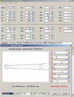
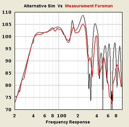
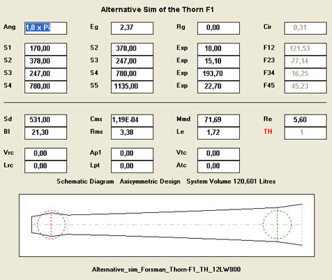
To make such alternative sim for your Thorn F1, I used your measurements to go from. First, I implied your measurement within the graphic ratio of HornResp. This gives a much easier comparison tool between model and measurement. After that I made some small changes in the HornResp input parameters to correct the volume at S2 and S4 and some small changes for the correct position of the point source ( lays within the cone). When you increase the volume at S2 one needs to compensate at S4 in order to keep the correct total internal volume of the enclosure. By using the exact frequency location of the peaks and dips of your measurements I tried to improve the model further. In the next picture you see the result (black) in combination with your actual measurement (red), all in the same plot ratio.
The input page looks like this:
Now you have an more accurate model you can see that by making the S2 area smaller (Cone Volume Correction) you can optimise the model to what you have modelled in the first place. I did so by decreasing the volume of S2:
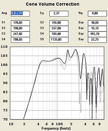
This example of the cone volume correction should bring it back to what you have simmed (freqeuncy response) in your original model. What this Cone Volume Correction will do is increase the compression at S2. Therefore the pressure minimums at S2, those of the 1/2 wavelength and full wavelength, will rise.
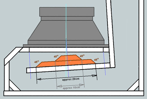
If you decide to experiment with the cone correction I made a quick sketch of how to start. You can experiment with smaller and larger shapes until you find the best solution.
Sorry I didn't reply earlier but (enough) time is sometimes difficult to find...
To be honest I think (just my opinion) that using Resonators/absorbing techniques only increases losses. I prefer to optimise the design rather than creating more losses. To me your 'dip problem' is the result of the difference between sim and design, like I stated earlier. I think it would be helpful to have a more accurate model to see what’s going on. It also help me
to explain what I meant with the cone volume correction.The volume within the cone is usually the main reason why the dip is (usually) larger in measurements compared to the sim. In other words the volume at S2 in the original model doesn’t represent the volume in reality. In my post#23 of the "SS15 or Tham 15?" thread I showed an example of an alternative way of simming the THAM. The alternative model shows the dip pretty accurate and looks similar to what one can measure from a standard Tham.
To make such alternative sim for your Thorn F1, I used your measurements to go from. First, I implied your measurement within the graphic ratio of HornResp. This gives a much easier comparison tool between model and measurement. After that I made some small changes in the HornResp input parameters to correct the volume at S2 and S4 and some small changes for the correct position of the point source ( lays within the cone). When you increase the volume at S2 one needs to compensate at S4 in order to keep the correct total internal volume of the enclosure. By using the exact frequency location of the peaks and dips of your measurements I tried to improve the model further. In the next picture you see the result (black) in combination with your actual measurement (red), all in the same plot ratio.
The input page looks like this:
Now you have an more accurate model you can see that by making the S2 area smaller (Cone Volume Correction) you can optimise the model to what you have modelled in the first place. I did so by decreasing the volume of S2:
This example of the cone volume correction should bring it back to what you have simmed (freqeuncy response) in your original model. What this Cone Volume Correction will do is increase the compression at S2. Therefore the pressure minimums at S2, those of the 1/2 wavelength and full wavelength, will rise.
If you decide to experiment with the cone correction I made a quick sketch of how to start. You can experiment with smaller and larger shapes until you find the best solution.
Last edited:
Thank you very much Djim!
Don’t apologize for not having time. This is hobby and that is something we do for the fun of it and when we have time.
I really appreciate that you are taking you time to explain in such pedagogic way. I must confess that I didn’t really get it the first time… Your simulations show your point in a excellent way.
I must do some experiments with this Cone Volume Compensation.
Regards
/Fredrik
Don’t apologize for not having time. This is hobby and that is something we do for the fun of it and when we have time.
I really appreciate that you are taking you time to explain in such pedagogic way. I must confess that I didn’t really get it the first time…
Your simulations show your point in a excellent way.I must do some experiments with this Cone Volume Compensation.
Regards
/Fredrik
- No I am not trying to cook rice pudding in the driver. The powerrating is close to a kilowatt so there is potential to heat things up. The problem is to get the food not to fly all over the kitchen...
Well, now I know that the cone can hold exactly 1,5 l of rice. And the hole cut out in the baffle can hold anther 0,99 l.
/Forsman
An externally hosted image should be here but it was not working when we last tested it.
Well, now I know that the cone can hold exactly 1,5 l of rice. And the hole cut out in the baffle can hold anther 0,99 l.
/Forsman
Hi Forsman,
When you make a 'perfect' (afterwards) cone volume correction it will cause a narrowing passage at the edge of the baffle cut out. The example I gave you in my post (last picture) has about a 2 Litre correction but should be at the correct height at the source point (see help-lines within the sketch). It should be enough for correction but without causing obstruction of the horn-path.
When you make a 'perfect' (afterwards) cone volume correction it will cause a narrowing passage at the edge of the baffle cut out. The example I gave you in my post (last picture) has about a 2 Litre correction but should be at the correct height at the source point (see help-lines within the sketch). It should be enough for correction but without causing obstruction of the horn-path.
Hi Djim
I would be pretty easy to do a cast in gypsum of the cone volume. Just cover the driver with plastic and pour the gypsum in it. When it has hardened it could be cut in half and placed with the cut towards the side walls and thus creating a funnel right under the driver with perfect cone volume compensation.
It is much easier though to do it your way Djim. Maybe I should start there. I just wish the temperature could raise a couple of degrees, minus 15 C this morning and the workshop isn’t insulated.
edit:
I don’t know if this can be another way of simulationg the effects of the cone volume. I took my 2,5 l and added 2500 cc to Vtc (front chamber volume) and 531 cm2 to Atc (front chamber average cross section). That gives me this result:
(grey: original, black: with frontchamber/cone volume)
Not as close to the real measurements as your sim Djim but closer than the original sim.
/Forsman
I would be pretty easy to do a cast in gypsum of the cone volume. Just cover the driver with plastic and pour the gypsum in it. When it has hardened it could be cut in half and placed with the cut towards the side walls and thus creating a funnel right under the driver with perfect cone volume compensation.
It is much easier though to do it your way Djim. Maybe I should start there. I just wish the temperature could raise a couple of degrees, minus 15 C this morning and the workshop isn’t insulated.
edit:
I don’t know if this can be another way of simulationg the effects of the cone volume. I took my 2,5 l and added 2500 cc to Vtc (front chamber volume) and 531 cm2 to Atc (front chamber average cross section). That gives me this result:
An externally hosted image should be here but it was not working when we last tested it.
(grey: original, black: with frontchamber/cone volume)
Not as close to the real measurements as your sim Djim but closer than the original sim.
/Forsman
Last edited:
Hi Forsman,
I’ll send you a nice Atlantic south-west depression this weekend to get rid off that cold.
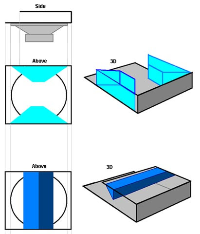
The acoustic air within a horn isn’t affected by relative small sized shapes compared to the relative large soundwaves in question. It’s all about the volume per section and not the shapes. In other words, it doesn't matter how the Cone Volume Correction looks like as long it sits in the correct position on the horn-path.
So you can use Cone Volume Correction also sideways like in this example picture;
I am not sure why the Atc/Vtc function gives different results but I guess it's because sims use a 'flat disk' instead of cone shape for simulating the driver's cone.
I’ll send you a nice Atlantic south-west depression this weekend to get rid off that cold.
The acoustic air within a horn isn’t affected by relative small sized shapes compared to the relative large soundwaves in question. It’s all about the volume per section and not the shapes. In other words, it doesn't matter how the Cone Volume Correction looks like as long it sits in the correct position on the horn-path.
So you can use Cone Volume Correction also sideways like in this example picture;
I am not sure why the Atc/Vtc function gives different results but I guess it's because sims use a 'flat disk' instead of cone shape for simulating the driver's cone.
Look what I have bought today.
I had never imagined that I ever should build loudspeakers out of Styrofoam but that I shall.
/Forsman
An externally hosted image should be here but it was not working when we last tested it.
I had never imagined that I ever should build loudspeakers out of Styrofoam but that I shall.
/Forsman
Do I think what you think? In that case I'm not sure it will work. The density/stiffness of the styrofoam doesn't look 'experimental correction' enough....I had never imagined that I ever should build loudspeakers out of Styrofoam but that I shall.
- Status
- This old topic is closed. If you want to reopen this topic, contact a moderator using the "Report Post" button.
- Home
- Loudspeakers
- Subwoofers
- Thorn F1 - a learning experiance with Tapped Horn