Hello
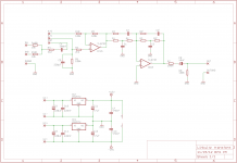
I'm interested in building the Linkwitz transform circuit shown at Rod Elliott's website:
http://sound.westhost.com/project71.htm
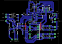
This project page has a very good article about this sort of subwoofer equalization. It has some schematics for a Linkwitz transform circuit so I drew a printed circuit board for it with the Eagle layout editor. I have access to a PCB manufacturing machine at my school and I'm going to use it to fabricate the board for me.
I've never used Eagle before, so I'm not sure if my beginner's design would have some obvious pitfalls.
I'm interested in building the Linkwitz transform circuit shown at Rod Elliott's website:
http://sound.westhost.com/project71.htm
This project page has a very good article about this sort of subwoofer equalization. It has some schematics for a Linkwitz transform circuit so I drew a printed circuit board for it with the Eagle layout editor. I have access to a PCB manufacturing machine at my school and I'm going to use it to fabricate the board for me.
I've never used Eagle before, so I'm not sure if my beginner's design would have some obvious pitfalls.
Attachments
I would look up some newer op-amps. Nothing exotic needed. I would also look into a few suggestions on improving the regulator circuit. Not much, for the use intended this is all quite workable but a bit has been learned in the past 20 years.
As you did not describe where this is to be mounted, let me assume in a stand alone box:
I like to mark drilling holes for mounting. I also prefer to put all the jacks on one side to make it fit in a box easier. For a board this small, I would be inclined to put the transformer, rectifiers, caps, and such all on the board. Why fool with point to point wire for the power supply? I would leave a tad more space between the lands.
Why are you using two positive regulators? I would use one positive, one negative. I would try not to have to use an output blocking cap. Doing tracking regulators could help that. It sort of depends on the amp it is feeding. If the amp has DC blocking, you don't need it here. I did not verify the circuit. I'll leave that to others.
Note, I have built these on perf board just fine. Point to point.
I understand there's a large number of audiophile-grade op-amp chips available, but since I see TL072 used in many DIY audio projects I'm inclined to think it would be a decent (and low-cost) choice.
At the moment I'm thinking of housing this circuit inside a stand-alone box, but I could also try if I could somehow fit it inside the subwoofer plate amp enclosure.
If it ends up having its own box I thought about powering it with two small DC wall cubes so I wouldn't have to deal with the mains voltage.
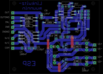
Thanks for the suggestion to put all connections into the same side of the board, I made another version of the PCB where I moved the output into a different place. I also replaced the TO-220 voltage regulators with TO-92 models as the operating current of this circuit would be minimal (to my understanding in the range of 5..10 mA?).
I'm not sure about the DC blocking capacitor, I need to check if I could find it from the amplifier's schematic. But I might still want to use this capacitor in case I would use this circuit with other amplifiers in the future.
At the moment I'm thinking of housing this circuit inside a stand-alone box, but I could also try if I could somehow fit it inside the subwoofer plate amp enclosure.
If it ends up having its own box I thought about powering it with two small DC wall cubes so I wouldn't have to deal with the mains voltage.
Thanks for the suggestion to put all connections into the same side of the board, I made another version of the PCB where I moved the output into a different place. I also replaced the TO-220 voltage regulators with TO-92 models as the operating current of this circuit would be minimal (to my understanding in the range of 5..10 mA?).
I'm not sure about the DC blocking capacitor, I need to check if I could find it from the amplifier's schematic. But I might still want to use this capacitor in case I would use this circuit with other amplifiers in the future.
Attachments
The TLO-72 was a great op amp in 1978. Almost revolutionary compared to a 741 or 318. (very static sensitive though) I used many of them in my time. Please, the NE5534 is a far better choice for today. You don't need anything expensive like the LME4562, which is today's super chip.
I have played the wall wart game. Yea, it can work. The power supply is just as critical as the rest of the circuit. You may even be able to power it with a single supply and a rail splitter. Moving the transformer away from the circuit is not a bad thing.
You are wise to shy away from the AC side of things if you are not experienced in mains safety. There are a lot of little of things I don't even think about, because I have done it for so long, that could lead to a very dangerous situation. Rod Elliot is pretty emphatic in identifying projects with mains involved that safe execution is your job. Even looking at a UL or CSA certified OEM product, unless you know what you are looking for, you won't see the detail that prevents bad things from happening to you.
I built sub-midbass crossover (lowpass/bandpass filter) with TL082's (dual TL072) and it sounded fine.
You may not want to process high frequencies with a TL072 due to it's slew rate, I think 12 or 15 microSeconds per volt.
.
But, I don't think I would be able to tell the difference either way.
.
Why 2 positive regulators???
Is one supposed to be 7915?
.
On same subject, I ran a car amp with a car battery to power subs in my living room.
Charged it slowly almost constantly.
Worked great until........battery blew up and puked acid all over the ceiling and walls.
So, battery is OK..actually is a very clean supply.
You could use 2 ...9V batteries.
.
Just don't use a lead/acid battery in your house.
Dave
Last edited:
DC power from batteries eliminate the AC 50/60 Hz (and harmonics) noise that must be filtered out in AC powered supplies, a very good thing, other than reliance on batteries, which loose the amount of power they can supply after each depletion, other than an initial "break in" period where they get slightly better before dropping off.Do batteries make good power supplies for hi-fi gear?
Is it feasible to be battery-powered but to do the battery charging when the audio circuits are off?
Ben
Battery powered pre-amps are no problem for long listening periods, but large battery banks are needed for power amps used at loud levels if no charging is done while listening.
That said, a single group 27 size marine battery can power a DC home stereo system for days with a single charge at "normal" 80 dB peaks.
The same battery could go dead in less than an hour with a sealed sub blowing 120 dB.
Thanks for battery information. It is reassuring to learn there is no mains hum!
But do (different kinds of) batteries act like giant filter capacitors? What kind of internal resistance? Benefits in combating mystery grounding issues? And audio quality design issues like that.
Long ago, we used to build pre-pre-pre-amps for moving coil phono cartridges featuring batteries. But that's a rather special application.
Thanks.
Ben
If you decide to put it inside the plate amp, there is a reasonable chance that you could pick off the supply voltage from inside the amp. It's likely to have a regulated supply for its line-level circuitry. Some plate amps have an internal split supply like +-12V that would be perfect.
Even if it doesn't have a split supply, you could tap off whatever DC supply that it does have, regulate that down, then derive a virtual ground with a resistive divider with capacitor bypass. That would be tidier than having external wall warts and wires.
Even if it doesn't have a split supply, you could tap off whatever DC supply that it does have, regulate that down, then derive a virtual ground with a resistive divider with capacitor bypass. That would be tidier than having external wall warts and wires.
Thanks to my nice teacher I finished making to PCB for the filter. The milling machine made some mistakes in cutting the board outline and also left half of the component holes undrilled (most probably operator's fault).
Anyway; I can finish the PCB by myself using a 0,8 mm Dremel drill.
Anyway; I can finish the PCB by myself using a 0,8 mm Dremel drill.
Attachments
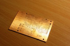
Perhaps it's just a photographic artifact, but it appears that the copper plate is a bit oxidized. You might want to remove that before soldering; otherwise the solder won't flow as well. You can soak it in a vinegar/salt/water solution, then thoroughly rinse in clean water after the copper becomes bright. Google for "chemistry with pennies" for proportions.
With your layout and fabrication, there will be a fair amount of capacitance between the various opamp pins, so start with an opamp that is fairly stable; don't go for a super high bandwidth one initially.
Enjoy!
With your layout and fabrication, there will be a fair amount of capacitance between the various opamp pins, so start with an opamp that is fairly stable; don't go for a super high bandwidth one initially.
Enjoy!
Perhaps it's just a photographic artifact, but it appears that the copper plate is a bit oxidized. You might want to remove that before soldering; otherwise the solder won't flow as well. You can soak it in a vinegar/salt/water solution, then thoroughly rinse in clean water after the copper becomes bright. Google for "chemistry with pennies" for proportions.
With your layout and fabrication, there will be a fair amount of capacitance between the various opamp pins, so start with an opamp that is fairly stable; don't go for a super high bandwidth one initially.
Enjoy!
Hello,
I don't see any signs of oxidization on the copper layer but it has some fingerprints on it. Better to clean it with some cleaning solvent after I finish the drilling.
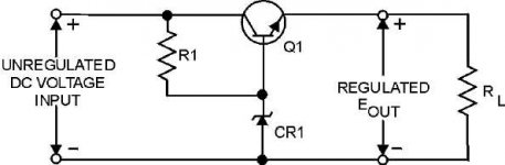
Also, I have measured the power supply rails on the plate amp. It has a double-sided supply of ±40 VDC. Unfortunately the maximum recommended input voltage for 78L15 is only 30 V. Maybe a simple series zener diode/transistor pre-regulator arrangement could be used to make the supply voltages suitable for 78L15.
Attachments
Your pre-regulator will work, but the transistor might need some heat-sinking, depending on how much current you are drawing. I wonder if the power transformer might have additional taps for lower voltages? I would be a little surprised if +-40V is the only voltage inside the plate amp, as they usually have some lower-voltage circuitry for auto-power-on and the like. But maybe not.
There exist linear regulators that can handle more than 40V, for example MAX5023/5024, LT3012, LR12, TL783. Some semiconductor companies are pretty good about giving you a few free samples. TI is certainly very generous in that respect.
There exist linear regulators that can handle more than 40V, for example MAX5023/5024, LT3012, LR12, TL783. Some semiconductor companies are pretty good about giving you a few free samples. TI is certainly very generous in that respect.
- Status
- This old topic is closed. If you want to reopen this topic, contact a moderator using the "Report Post" button.
- Home
- Loudspeakers
- Subwoofers
- ESP Linkwitz transform PCB