Hey guys, after a long time being away from this hobby, I find myself over my head in trying to build not 1 but 2 subwoofer boxes. What started as discussion with a friend of how I wanted to make a better box for my car turned into a double projectfor me and my friend!
I have to (apparently, the MDF has been already bought) build 2 sub boxes for 2 different drivers for different purposes! I've been interested in car audio since I was kid, but my friends project is for home, using a car sub!!!! As rushed as all seems, the amp is en route and should arrive in 10-15 days!
I'm making this a double project, since both boxes will be built alongside. Now, the car sub which is for my Land Rover is a 10" Audiobahn AW101T. It's in decent box, which some guys built me some time ago, but I always wanted a slot port box!
My friends box is to be using a Pioneer TSW309 S4 car sub in simillar design box, but for home use. Now this is where I'm not sure if I've done my calculations right. Budget constrains force me to use the mentioned drivers for both projects, one is existing the other is in my friend's budget. 50 euro for 19mm thick MDF which is 3.6x1.8 meters - the sheet has been bought already!
I've been reading the forum a lot lately and was wondering if you guys can help me out with the calculations and maybe some tips? I've built my last sub box 5 years ago, from waste MDF boards, even more troubling - this last box was also my FIRST one!!! I don't want to mess up badly with those 2 projects as there's a friend involved and I don't mind screwing my car sub design, but his HAS to work!
First, I want to ask for your ideas or recommendation at this stage? Is it too crazy of an idea to work? Should i reconsider design, driver or anything to try to avoid or focus on? The driver's Fs is 40hz, I'm tuning it to 34hz
I will provide you with design templates, pics and calculations after I figure the upload feature.
Specs can be found here, including recommended box volume and port dimensions.
Pioneer TS-W309S4 Champion Series 12" 4-ohm subwoofer at Crutchfield.com
Or here Pioneer TS-W309S4 (TSW309S4) 12" Single 4 Ohm Champion Subwoofer
Crutchfield's recommended box volume and port dimensions gives a box tuned to 40.5 Hz.
.
This box has a 4.4 dB hump at ~57 Hz, is 3 dB down from that at ~ 41 Hz, 6 dB down at ~ 36 Hz and 10 dB down at ~ 30.5 Hz.
The recommended 1.5 ft.^3 (42.5 liter) box W/ 76 mm X 223 mm Port would be
OK for a car with it's Cabin gain.
.
For home stereo you need at least a 3 ft.^3 (85 L) box.
The port will need to be more like 101 mm ID, with flares if possible.
That will put out well, down to ~ 25 Hz with a 101 mm ID X 300 mm port.
101 X 300 mm tunes 3 ft. to ~ 28 Hz
Better, use a 101mm ID X 450 mm long port for flatter response.(23 Hz tuning)
Or, use a 4 ft.^3 (113 L) box with a 101 mm ID X 245 mm long port (26 Hz)
Even better a 5 ft.^3 (140 L) box with a 101 mm ID X 225 mm long port.(24 Hz)
If you want to use a slot port, with an 85 L box it will be long and probably have to turn a corner.
For instance a 250 mm wide X 40 mm tall slot port will need to be between 350 and 550 mm long.
.
I imagine this would require a steep High Pass filter at 20 Hz or more to protect the speaker from over-extension.
Like so many car woofers, I can not seem to find all the specs such as DC resistance, Inductance, X-Max, Sd, Cms and the few more that are required to really model this driver.
I suspect that in a large ported box you could not drive it with much power, maybe 100-150 W max, but the smaller Car-sub box helps to protect the speaker at higher powers.
.
Bottom line, you could make a decent home stereo subwoofer with a pair of 3 ft.^3 boxes, but you will need to have electronics to protect the speaker from hitting it's limits. (high pass filter and power limiter)
For Home Theater (watching TV & Movies) it may not be a good choice.(both the driver and a Bass Reflex box)
Hope this helps,
Dave
Also, don't believe everything you read, try it yourself and learn.
Ah, yes, as I feared! My approach is flawed, Shadydave as you said I can actually make the box bigger and keep it simple! There will be electronics involved. The home sub will be driven by a dedicated Bash 300W plate amp. There's not much I can do there - it's in transit.
I am using Bass Box 6 to model my boxes and manged to find some details on the Pioneer sub, here are the specs entered / calculated by Bass Box:
Fs = 39.5 Hz
Qms = 12.47
Vas = 1.064 cu.ft
Cms = 0.00745 cm/N
Mms = 217.9 g
Rms = 4.338 kg/s
Xmax = 10.4 mm
Xmech = 15.6 mm
P-Dia = 260.7 mm
Sd = 0.0534 sq.m
P-Vd = 555 cu.cm
Qes = 0.697
Re = 3.189 ohms
Le = 2.33 mH
Z = 4 ohms
BL = 15.73 Tm
Pe = 400 watts
Qts = 0.66
no = 0.257 %
1-W SPL = 86.24 dB
2.83-V SPL = 90.24 dB
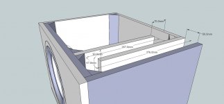
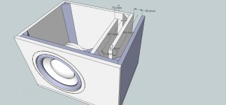
X-max is really a guesstimate on my part, the program then suggests X-mech. Vas is taken from the manufacturer, Qts is also from the manufacturer. I know this sub is over-rated and I don't have equipment to test it even if I knew how! I've worked with Pioneer subs before and they are very well balanced at least to my ear and achieve good sound in moderate enclosures. However, I am looking at this from a car audio point of view when I shouldn't! The box design, I have currently, employs a single 180 degree port bend, while keeping all measurements as equal as possible, but actually making the box bigger will ease the construction and port dimensions.
The box dimensions so far as follows:
H 420mm x W 560mm x D 420mm
MDF thickness - 19mm
Bass Box gives the following results:
Type: Vented Box
Shape: Prism, square
Vb = 59145 cu.cm
Fb = 34.27 Hz
QL = 6.582
F3 = 40.25 Hz
Fill = heavy
No. of Vents = 1
Vent shape = rectangle
Vent ends = one flush
Hv = 382 mm
Wv = 50 mm
Lv = 732 mm
QLv = 7
Please note that the actuall desing has a double front baffle, so physical dimenssions are slightly larger. But you can see it in the attachments.
At this stage, I am beginning to doubt the whole design of the box. Any suggestion or pointers?
I am using Bass Box 6 to model my boxes and manged to find some details on the Pioneer sub, here are the specs entered / calculated by Bass Box:
Fs = 39.5 Hz
Qms = 12.47
Vas = 1.064 cu.ft
Cms = 0.00745 cm/N
Mms = 217.9 g
Rms = 4.338 kg/s
Xmax = 10.4 mm
Xmech = 15.6 mm
P-Dia = 260.7 mm
Sd = 0.0534 sq.m
P-Vd = 555 cu.cm
Qes = 0.697
Re = 3.189 ohms
Le = 2.33 mH
Z = 4 ohms
BL = 15.73 Tm
Pe = 400 watts
Qts = 0.66
no = 0.257 %
1-W SPL = 86.24 dB
2.83-V SPL = 90.24 dB
X-max is really a guesstimate on my part, the program then suggests X-mech. Vas is taken from the manufacturer, Qts is also from the manufacturer. I know this sub is over-rated and I don't have equipment to test it even if I knew how! I've worked with Pioneer subs before and they are very well balanced at least to my ear and achieve good sound in moderate enclosures. However, I am looking at this from a car audio point of view when I shouldn't! The box design, I have currently, employs a single 180 degree port bend, while keeping all measurements as equal as possible, but actually making the box bigger will ease the construction and port dimensions.
The box dimensions so far as follows:
H 420mm x W 560mm x D 420mm
MDF thickness - 19mm
Bass Box gives the following results:
Type: Vented Box
Shape: Prism, square
Vb = 59145 cu.cm
Fb = 34.27 Hz
QL = 6.582
F3 = 40.25 Hz
Fill = heavy
No. of Vents = 1
Vent shape = rectangle
Vent ends = one flush
Hv = 382 mm
Wv = 50 mm
Lv = 732 mm
QLv = 7
Please note that the actuall desing has a double front baffle, so physical dimenssions are slightly larger. But you can see it in the attachments.
At this stage, I am beginning to doubt the whole design of the box. Any suggestion or pointers?
Attachments
Ok, new results.
Following Shadydave's recommendations and Bart's observations I have remodeled the box for the Pioneer sub.
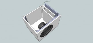
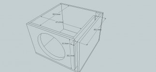
I've got info on the room the sub will be playing in and its huge! It's a basement floor, tiled floor with some carpets, its surrounded by reinforced concrete walls and columns, being part of the foundation of the house. I think this will be vibrating like hell! I spent half of today thinking on the possible issues or effects once the sub is placed in the room. As mentioned, I redesigned the box, made it larger, kept the slot port but got rid of the bends! You can have a look at the attachments.
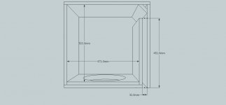
New box measurements:
Physical dimmensions H 420mm x W 560mm x D 560mm
Since the front baffle is double thickness, measurements for simulation used are:
H 420 x W 560 x D 541 (note, I am using 19mm MDF)
Bass Box 6 results:
Type: Vented Box
Shape: Prism, square
Vb = 87455 cu.cm
Fb = 26.85 Hz
QL = 6.582
F3 = 41.86 Hz
Fill = heavy
No. of Vents = 1
Vent shape = rectangle
Vent ends = one flush
Hv = 382 mm
Wv = 32 mm
Lv = 452 mm
QLv = 7
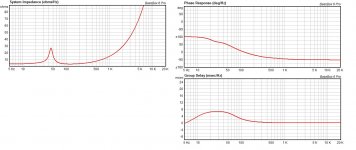
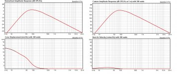
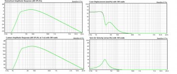
I am adding the response curves from Bass Box, I figure some of the data is off, there are no passive or active filter elements considered in the response curves!
Since the box got bigger, I assume I will have to use some bracing! I have never used bracing before and I'm not sure where to put it! Are there any general guides to follow regarding bracing?
P.S. the schematic is incomplete due to some 45s missing as well as possible bracing, but I did this in hurry!
Following Shadydave's recommendations and Bart's observations I have remodeled the box for the Pioneer sub.
I've got info on the room the sub will be playing in and its huge! It's a basement floor, tiled floor with some carpets, its surrounded by reinforced concrete walls and columns, being part of the foundation of the house. I think this will be vibrating like hell! I spent half of today thinking on the possible issues or effects once the sub is placed in the room. As mentioned, I redesigned the box, made it larger, kept the slot port but got rid of the bends! You can have a look at the attachments.
New box measurements:
Physical dimmensions H 420mm x W 560mm x D 560mm
Since the front baffle is double thickness, measurements for simulation used are:
H 420 x W 560 x D 541 (note, I am using 19mm MDF)
Bass Box 6 results:
Type: Vented Box
Shape: Prism, square
Vb = 87455 cu.cm
Fb = 26.85 Hz
QL = 6.582
F3 = 41.86 Hz
Fill = heavy
No. of Vents = 1
Vent shape = rectangle
Vent ends = one flush
Hv = 382 mm
Wv = 32 mm
Lv = 452 mm
QLv = 7
I am adding the response curves from Bass Box, I figure some of the data is off, there are no passive or active filter elements considered in the response curves!
Since the box got bigger, I assume I will have to use some bracing! I have never used bracing before and I'm not sure where to put it! Are there any general guides to follow regarding bracing?
P.S. the schematic is incomplete due to some 45s missing as well as possible bracing, but I did this in hurry!
Attachments
Don't worry about the 45's in the corners. (except by the port, like you have.)
Most plate amps have a high pass filter around 20 Hz. So you should be good there.
Braces should be designed to stop the walls from flexing. Look around for pictures of DIY subs for a better idea of bracing. If you can fit them in every 200 mm or so that should do quite well. I don't like MDF for braces, I suggest plywood as it is stiffer. (MDF will work, you just need to use a bigger piece.)
Totally different picture:
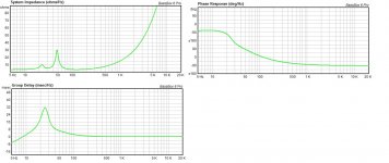
That looks more like what I'd expect. If you could post a pic of the impedance also, showing the two peaks of a br box, it could be helpful for a comparison.
Ok, I may have screwed up with the software 
There's an option that says "include vent resonance peaks in all relevant graphs" In the previous graphs this option was ON. I am still trying to figure out some of the options, so I am still learning...
Now, with this option OFF, this is how the graphs look and the resulted frequencies:
Type: Vented Box
Shape: Prism, square
Vb = 87455 cu.cm
Fb = 28.46 Hz
QL = 6.582
F3 = 25.44 Hz
Fill = normal
No. of Vents = 1
Vent shape = rectangle
Vent ends = one flush
Hv = 382 mm
Wv = 32 mm
Lv = 452 mm
QLv = 7
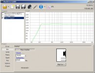
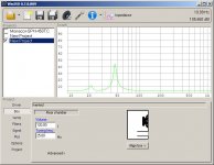
If things are really that bad I think I will have to start over. I think I ll double check with WinISD
There's an option that says "include vent resonance peaks in all relevant graphs" In the previous graphs this option was ON. I am still trying to figure out some of the options, so I am still learning...
Now, with this option OFF, this is how the graphs look and the resulted frequencies:
Type: Vented Box
Shape: Prism, square
Vb = 87455 cu.cm
Fb = 28.46 Hz
QL = 6.582
F3 = 25.44 Hz
Fill = normal
No. of Vents = 1
Vent shape = rectangle
Vent ends = one flush
Hv = 382 mm
Wv = 32 mm
Lv = 452 mm
QLv = 7
If things are really that bad I think I will have to start over. I think I ll double check with WinISD
Attachments
Sorry duanebrow, internal braces have exactly the same pressure on both sides!I don't like MDF for braces, I suggest plywood as it is stiffer. (MDF will work, you just need to use a bigger piece.)
In other words, braces don't flex by themselves.
The only panels in an enclosure that will suffer from flexing are panels that have an unequal pressure between the two sides.
For basreflex enclosures that are usually the panels facing the outside and the basreflex tunnel.
For this reason braces can be made of less stiff (cheaper) materials.
When made out of the same material the thickness of the braces can less if the attachment points are enforced/supported.
Last edited:
Good thing you asked for it, I don't like the looks of the impedance response. I was under the impression that both peaks should be equal for optimum performance¿... If you could post a pic of the impedance also, showing the two peaks of a br box, it could be helpful for a comparison.
Attachments
Sorry duanebrow, internal braces have exactly the same pressure on both sides!
In other words, braces don't flex by themselves.
The only panels in an enclosure that will suffer from flexing are panels that have an unequal pressure between the two sides.
For basreflex enclosures that are usually the panels facing the outside and the basreflex tunnel.
For this reason braces can be made of less stiff (cheaper) materials.
When made out of the same material the thickness of the braces can less if the attachment points are enforced/supported.
I agree with you, for a brace like you have pictured. And it is just my preference to use Plywood when I can. When I wrote my post, I was thinking about "cross bracing" (for lack of a better term). Lets go back to what flexes on a box. The corners can't flex because they are attached to another panel. So the most flexing in a box will be the center of the largest panel. By simply running a brace from the center of the panel to the opposing panel all flexing in the center of the panel can be stopped. In this case the brace can flex if it is not strong enough to withstand the pressure exerted on it by the sides. Both braced panels now flex as much as one 1/4 of the size. By using more of these braces on the panels the results greatly increase. The law of diminishing returns applies of course.
OK guys, there's been an update! I managed to somehow explain to my friend that there's a difference between sub for car audio and for home audio! I was showing him some examples and by at one point after I showed him the Eminance Lab 12 he stopped me and said "You convinced me, I ordered it already" !
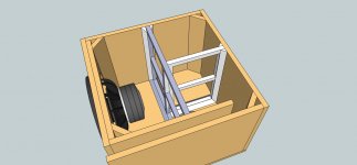
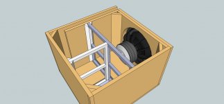
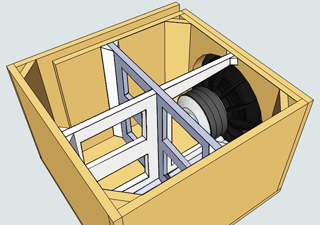
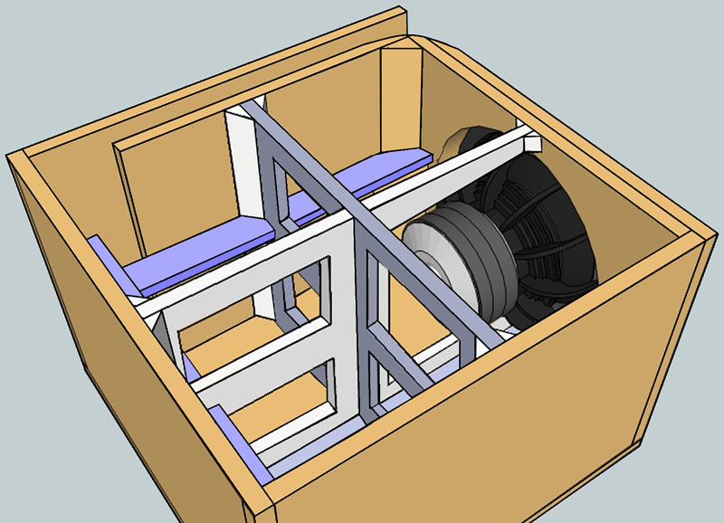
So now I am pretty excited, since I never thought I would be able to get this speaker here in this country and is not something I have the loose change for to experiment! I've taken an interest in the bracing discussion earlier, I have some updated designs. I would like to hear opinions about the design... talking about the braces. The box with the Lab 12 will be the same as last time, 100.3 liters total, tuned to 28Hz, single slot 42w x 382h x 500-520l mm. I plugged the numbers both in Bass Box and WinISD and the results are almost identical! Pretty flat response but will have to make a steep high-pass at around 25Hz to protect the sub. I have no idea about crossovers, I am willing to try and make one, but have no idea where and how to start. But that for later on.... I am more interested in the bracing as I want to finish the design so I can take the dimensions and cut the MDF.
I am not sure wheter or not I am going to be able to find or use different material for bracing. So far the cost of the whole thing went more than double with the new driver! I think I can find plywood but can't really count on it. So far I figured I reinforce the box with something similar to what Djim proposed, however with some minor modifications. If I'm limited to 19mm MDF, I provide for 2 extra panels to be used as braces inside. They will reinforce the back, port wall and side of the box. The panels will be glued then bolted from the sides, bottom and top part. In my view this will reduce flex to a minimum without making the insides too crowded
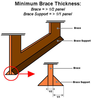
The base support is also from 19mm MDF so basically brace and brace support will be 1/1 panel thickness both! Would that be a problem? Also, please advise if the current brace design isn't an overkill?
So now I am pretty excited, since I never thought I would be able to get this speaker here in this country and is not something I have the loose change for to experiment! I've taken an interest in the bracing discussion earlier, I have some updated designs. I would like to hear opinions about the design... talking about the braces. The box with the Lab 12 will be the same as last time, 100.3 liters total, tuned to 28Hz, single slot 42w x 382h x 500-520l mm. I plugged the numbers both in Bass Box and WinISD and the results are almost identical! Pretty flat response but will have to make a steep high-pass at around 25Hz to protect the sub. I have no idea about crossovers, I am willing to try and make one, but have no idea where and how to start. But that for later on.... I am more interested in the bracing as I want to finish the design so I can take the dimensions and cut the MDF.
I am not sure wheter or not I am going to be able to find or use different material for bracing. So far the cost of the whole thing went more than double with the new driver! I think I can find plywood but can't really count on it. So far I figured I reinforce the box with something similar to what Djim proposed, however with some minor modifications. If I'm limited to 19mm MDF, I provide for 2 extra panels to be used as braces inside. They will reinforce the back, port wall and side of the box. The panels will be glued then bolted from the sides, bottom and top part. In my view this will reduce flex to a minimum without making the insides too crowded
The base support is also from 19mm MDF so basically brace and brace support will be 1/1 panel thickness both! Would that be a problem? Also, please advise if the current brace design isn't an overkill?
Attachments

The 45's at the sides of the front baffle are just using up airspace. Since the corners are basically a brace. You don't need to use any type of mechanical fasteners on the braces, the glue is stronger than anything else in the box. And MDF likes to split when anything is driven into the end grain. Lots of clamps and glue and you are all set.
It looks fine in the drawing, but make sure that you have clearance for the drivers vent.
Btw, Lab 12 drivers are very nice. Is he getting one of the new 4 ohm versions? I know a guy that got two of them before they were released. Seems very pleased with them.
It looks fine in the drawing, but make sure that you have clearance for the drivers vent.
Btw, Lab 12 drivers are very nice. Is he getting one of the new 4 ohm versions? I know a guy that got two of them before they were released. Seems very pleased with them.
- Status
- This old topic is closed. If you want to reopen this topic, contact a moderator using the "Report Post" button.
- Home
- Loudspeakers
- Subwoofers
- Help me out here