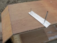
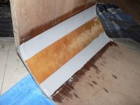
Did the rounded port now, had to start over 4 times trying to get it right!
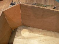
You can see at the short side of the bend, it didn't pull close.
Elastic band isn't working good here either.
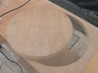
The darker color is from wetting the wood for an hour, to get it flexible.
Inner radius is 110mm (4.33")

Four times trying again later:
Pulling from under a strong piece of aluminum helped a lot, this way the pulling is about equal at both sides of the bend.
Not perfect but I left it like this. Tomorrow I'll see how it holds up...

You can see at the short side of the bend, it didn't pull close.
Elastic band isn't working good here either.
The darker color is from wetting the wood for an hour, to get it flexible.
Inner radius is 110mm (4.33")
Four times trying again later:
Pulling from under a strong piece of aluminum helped a lot, this way the pulling is about equal at both sides of the bend.
Not perfect but I left it like this. Tomorrow I'll see how it holds up...
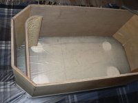
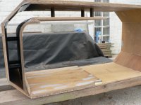
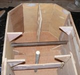
Just had a look and thinking that this is a 'test box' it's pretty complicated...
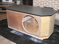
Placed the port in the box and it doesn't come out very well.
If I place it at the 75mm distance then between the curve and the 45° angle there are only 65mm.
The back wall is about 88mm from the curve.
It's also 'over curved' (more then a quarter circle) Guess I thought it might return a bit to it's original state but no, it didn't move a bit when releasing the five bands.
hmmm, I'll have to find a fix for that.
It was to be expected that a diy curve wouldn't be perfectly round.
Attachments
It is pretty solid and very heavy. I recommend "Moving Men" (teflon discs) for moving it on carpet, etc. The center shelves are a perfect size for electronics and the back has knock-outs for cords.
corner tv stand
corner tv stand
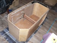
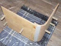
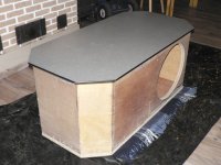
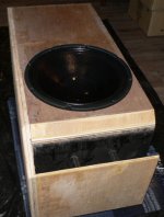
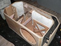
Had a few other things first so this is not progressing as wanted but almost there.
The port needs to be opened and a few extra braces here and there from leftover sheet.
Before I close up the box forever, input is most welcome! Probably will glue the table top on Tuesday.
Idea's on the finishing tough of the box? I would like it to look not too heavy, blend a bit with the floor or surroundings and maybe even difficult to see that it's a sub.
Attachments
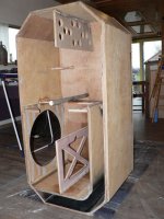
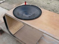
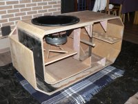
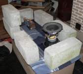
Everything is glued. Weighed the top down with about 300 pounds concrete blocks and a few other things.
I hope to put in the woofer today and throw in a cable through the BR duct to have a quick listen/feel.
For the finishing of the outside I would like to use some sort of paint that covers small irregularities and sticks very well, because I would use it to glue fiberglass wallpaper at the same time.
Then paint it mat black. What do you think about this?
Connection will be at the bottom, there will be shallow feet with felt to protect the floor somewhat.
Attachments
Honestly?... a bit on the thin side, I guess the amp should be bridged to put out 600W in to 8Ω. Now I'm using one channel so only 100W @ 8Ω
Bridging involves opening the amp and change a few things/wires. Have to dig out the plan, it's a DIY amp from Velleman.
I wouldn't say I'm disappointed because there is no tweaking/tuning what so ever but I thought I would have been pleasantly surprised...
If I listen closer to the woofer it sounds very powerful, effortless. The port doesn't put out much sound at all so I guess the tuning is indeed lower then most music puts out, that's a good sign.
Haven't had much time yet to test/experiment.
Any pointers?...
maybe you are used to listen to a sub in the corner or near wall.
that makes a lot of difference.
a while ago i made a sub table and was not happy with the results.
now ive placed it near the wall next to the sofa.
now i am much hapier with the sound (and my neigbours too )
)
if your worried its tuned to low,you could cut of a piece of the "pipe"
that makes a lot of difference.
a while ago i made a sub table and was not happy with the results.
now ive placed it near the wall next to the sofa.
now i am much hapier with the sound (and my neigbours too
)if your worried its tuned to low,you could cut of a piece of the "pipe"
yes, two small subs in fact.
The driver was brand new, after an hour of 50cent at only 50W (not my style, just for the bass) it sounded much better.
I guess I should give it ten hours of break in and report back.
I wouldn't cut the port but I'd rather fill the box with bricks or bags of sand to alter the tuning.
this I first want to decide through impedance measurement.
Thanks for your thoughts!

Maybe…. Nominal impedance versus Zmin for instance and that a dummy load is a static load and not an inductive load. In other words some amps don't measure as well with a static load and could be judged wrongly. I would use the Velleman modules in bridged, just like the VC's (just like you modelled). Your Velleman modules/power supplies also perform better in bridged instead of each module loaded with a 3.7 Ohm load. Nevertheless, the bridged Velleman modules are still way below the capabilities of the driver(s) and I prefer to have it the other way around.
Nominal impedance versus Zmin for instance and that a dummy load is a static load and not an inductive load. In other words some amps don't measure as well with a static load and could be judged wrongly. I would use the Velleman modules in bridged, just like the VC's (just like you modelled). Your Velleman modules/power supplies also perform better in bridged instead of each module loaded with a 3.7 Ohm load. Nevertheless, the bridged Velleman modules are still way below the capabilities of the driver(s) and I prefer to have it the other way around.Thanks Djim, much appreciated.
I was really unsure about this.
Then there's the bl factor which just came to mind. That too is best when coils in series I guess?
(What's a good site/book to learn about T&S parameters and really understand them?)
I'm trying very hard to use some time to measure the resonance/impedance now. Did some sine testing and found out there's a lot of stuff that will need to be glued/tightened or moved in the house. This was only at about 10W.
At first sight the tuning is about 18hz.
My Volt meter jumps around so I might have to solder a rectifier and measure dcV. But I think the scope would be a better choice since it's easy to see the relationship between resistor and driver to determine resonance accurately. (bought it very cheaply)
Thanks guy's, where would I be without all your help!
I was really unsure about this.
Then there's the bl factor which just came to mind. That too is best when coils in series I guess?
(What's a good site/book to learn about T&S parameters and really understand them?)
I'm trying very hard to use some time to measure the resonance/impedance now. Did some sine testing and found out there's a lot of stuff that will need to be glued/tightened or moved in the house.
This was only at about 10W.At first sight the tuning is about 18hz.
My Volt meter jumps around so I might have to solder a rectifier and measure dcV. But I think the scope would be a better choice since it's easy to see the relationship between resistor and driver to determine resonance accurately. (bought it very cheaply)
Thanks guy's, where would I be without all your help!
- Status
- This old topic is closed. If you want to reopen this topic, contact a moderator using the "Report Post" button.
- Home
- Loudspeakers
- Subwoofers
- Pivoting TV-stand/HT-sub/stealth corner