422 duno if in or ex tax
Behringer NU 6000 DSP iNuke
anders baxshop.nl
are the monacors 8 or4 ohm per coil?
if 8 per coil you coild wire 2 coils series +2 speakers parelel for 8 ohm bridge.
Behringer NU 6000 DSP iNuke
anders baxshop.nl
are the monacors 8 or4 ohm per coil?
if 8 per coil you coild wire 2 coils series +2 speakers parelel for 8 ohm bridge.
Last edited:
Thanks.
The voice coils are DVC 4Ω+4Ω per driver. So either 8Ω or 2Ω if using both coils on the driver.
Or I can use the one or the other coil on the driver but I don't like that, it feels like a waste of potential.
Should I loosen the suspension and do T&S measurements or can I rely on the specifications from the manufacturer?
Last edited:
If you only use one coil in a dual coil driver, the power handling is reduced and the T/S parameters would be different, at least Re and Inductance.
.
I had been looking into this for using one coil as a feedback element in a DSP based motion control system.
.
I finally decided it was a waste of time.
Much better to design an efficient horn where the driver is only using a small amount (1/4 or less of it's electrical power handling capability).
.
Like the 19 ft. Lab 12 TH that hits X-max at 120 Watts and 125 dB SPL (out of 400 watt rms speaker rating).
Or the Lab 12 OD-ML-TL (less than 50% power)
Dave
.
I had been looking into this for using one coil as a feedback element in a DSP based motion control system.
.
I finally decided it was a waste of time.
Much better to design an efficient horn where the driver is only using a small amount (1/4 or less of it's electrical power handling capability).
.
Like the 19 ft. Lab 12 TH that hits X-max at 120 Watts and 125 dB SPL (out of 400 watt rms speaker rating).
Or the Lab 12 OD-ML-TL (less than 50% power)
Dave
Last edited:
Had to do a lot of learning on Sketchup, pfff
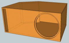
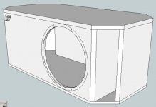
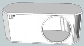
This is where I'm at now and what I would build.
I would like to get as much comment as possible, trying to do this the right way. Thanks!")
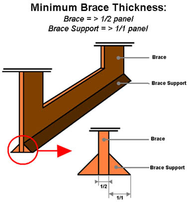
(bracing is not drawn but will be added of course)
Is the driver placement important in relation with the port?
This is where I'm at now and what I would build.
I would like to get as much comment as possible, trying to do this the right way. Thanks!
(bracing is not drawn but will be added of course)
Is the driver placement important in relation with the port?
Attachments
Last edited:
Hi again
Some bad new and some good...
Bad news is, I'm not feeling confident enough starting this difficult construction.
Good news, I'm starting Monday trying to build a coffee table from an old coffee table, only the top stays. With specs very close to the ones posted above!
One question though, how much space does the air duct in the magnet need? (cooling hole in magnet)
The BR duct will go behind it, how close can it get?
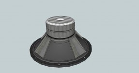
Ive done your driver for you. Its not perfect, the bolt holes are 6mm instead of 8mm diameter, and the motor magnet stack is 200mm diameter instead of 220mm. You'll have to blame the kids, sorry, and I dont have the time to correct the magnet stack. It should do though, all the important measurements are correct, the basket diameter is correct, as is the basket rim depth, and the drivers overall depth.
Hope its ok. I just need your e-mail so I can send you the driver file.
You need to keep clear of the VC vent at least equal to its diameter, and personally I would advise to double it. One point though, I'm not sure having it directly opposing the port itself is ideal, but if thats how it has to be then I guess to have to work with what you have. Looking at your model in your previous post though, if thats how it is then you should be absolutely fine.
Attachments
Last edited:
I'll use 18mm plywood.
Does this have to be 'void free'?
There's a lot of talk about that now but when I started my first box building, MDF was THE material to use, now suddenly it's no longer as good it seems¿
I have two big sheets of plywood of 18mm just standing there and would like to use it as it costs no extra money but I'm sure there are imperfections in it, that's even visible from the sides.
What would be the consequence? Or can I safely use it?

I'd like to use kerf bending for the port.
Does this have to be 'void free'?
There's a lot of talk about that now but when I started my first box building, MDF was THE material to use, now suddenly it's no longer as good it seems¿
I have two big sheets of plywood of 18mm just standing there and would like to use it as it costs no extra money but I'm sure there are imperfections in it, that's even visible from the sides.
What would be the consequence? Or can I safely use it?
I'd like to use kerf bending for the port.
Hi Bart,
This surely would be a nice driver for a large built-in tapped horn.
Looking at your drawing in Post #24: I don't see a technical reason for a 45 degree bend in the duct. If you don't need it for the space you're working with just add the volume to your box and make it a 90 degree corner. It would also be nice to add at least one divider - preferably two - lengthwise into the duct to stiffen the boards.
Plywood is the preferred material for any speaker that will be moved around a lot. Otherwise, MDF would be fine. For a vented enclosure the quality of the plywood is not quite as important as for a horn, but you don't want any large voids, or delaminations.
Regards,
This surely would be a nice driver for a large built-in tapped horn
.Looking at your drawing in Post #24: I don't see a technical reason for a 45 degree bend in the duct. If you don't need it for the space you're working with just add the volume to your box and make it a 90 degree corner. It would also be nice to add at least one divider - preferably two - lengthwise into the duct to stiffen the boards.
Plywood is the preferred material for any speaker that will be moved around a lot. Otherwise, MDF would be fine. For a vented enclosure the quality of the plywood is not quite as important as for a horn, but you don't want any large voids, or delaminations.
Regards,
Hi Bart,
I agree with Oliver. There are AES studies and other studies that prove MDF has slightly better acoustic properties compared to plywood but in general the differences are negligible for subwoofers. It all comes down (quiet literally with that kind off driver) to your design/building qualities. If weight is not a problem try to use 22mm MDF.
It’s a heck of a TH driver but it needs very large volumes if you want to make it work below 20Hz. In case anyone considers the SPH-450TC for TH use, I have to warn you about the suspension, the spider. It’s designed in period (late 90ties) when extreme excursions were not common yet and therefore has some weak spots in the spider.
Hi Djim, thanks for clarifying.
I'll be using 18mm multiplex, left over from years ago and standing ready for cutting here at home.
I'll try to cut it myself but probably will wind up using it only for the port and braces as the external panels need to be very straight and at an angle of 67.5°
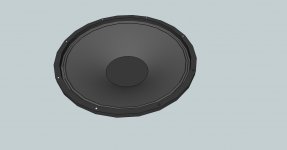
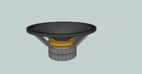
I'm building some kind of a test box out of a coffee table.
Someone recommended me to do so first...
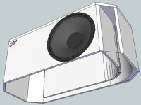
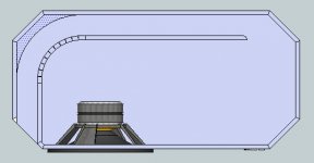
Drawings and a big thanks to Moonfly again!
Sexy driver in the boring box now:
I'll be using 18mm multiplex, left over from years ago and standing ready for cutting here at home.
I'll try to cut it myself but probably will wind up using it only for the port and braces as the external panels need to be very straight and at an angle of 67.5°
I'm building some kind of a test box out of a coffee table.
Someone recommended me to do so first...
Drawings and a big thanks to Moonfly again!
Sexy driver in the boring box now:
Attachments
Hi Bart,
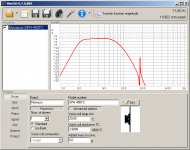
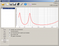
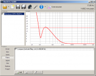
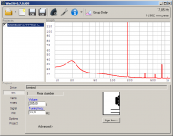
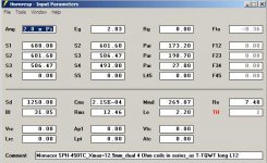
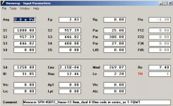
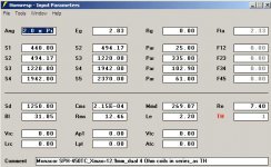
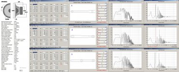
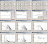
I'll attach Hornresp Input screens for a TH and bjorno's favorites: the T-TQWT and the T-TQWT/Long L12 (offset driver). These are just entry examples for your information. For home use I would probably go fot the T-TQWT/Long L12, but bjorno may have some different ideas, maybe he'll chime in?
Regards,
Attachments
Hi Bart,
I'll attach Hornresp Input screens for a TH and bjorno's favorites: the T-TQWT and the T-TQWT/Long L12 (offset driver). These are just entry examples for your information. For home use I would probably go fot the T-TQWT/Long L12, but bjorno may have some different ideas, maybe he'll chime in?
Regards,
Hi Oliver,All
I noticed your sub suggestions already
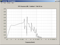
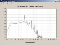
Yesterday : Here follows a few things I would prefer done a bit differently: I labeled your designs with # 1,2 and 3 (Shown in the first of two pictures)I try to make simulations where if followed do not need any EQ or signal-delay units, thus an ordinary plate amp would be quite sufficient.
Your first suggestion depicts a Tapped Horn,: No thumbs-down comment for this design as it have a good Main-Pulse FR that is IMO easy to EQ together with the needed necessary signal-delaying, in order to make a good integration with the Mains.
To ~equate the System cost of an EQ+Delay added to a single Driver TH with large separation of the Pre and Main Pulses:
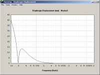
I suggest to bet on using two drivers instead in a slightly smaller OD_T-TQWT with IMO promising superior FR/BW performance and at max input Power the difference would be less than 2 dB in favor for the TH.
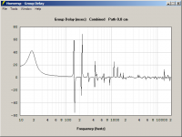
Your second suggestion have in my taste a too large Gldy at 80 Hz if no signal-delays are available or EQ'd to a lesser BW at ~80 Hz. Unless not XO'd lower than 80 Hz: A stuffed single fold would IME not be able smooth out the present peak:
I try to keep the Gldy lower than ~9.4 ms at 80 Hz allowing the use of a simple 180 degree variable phase control to minimize the always occurring acoustic XO ripple: This applies only when the sub is occupying the same wall as the Main Speakers.
The third long T-TQWT is IMO a perfect desing (with a very low XO Gldy) reaching above 100Hz:
Compared with a ML-QWP that only have a small edge concerning the in-band SPL capability but would have a very similar lower FR end when both designs are HPF protected.
b
Attachments
Hi bjorno,
Thanks for taking a look at my suggestions above.
I like your ML-QWP (the one on the right with #3). Would it be possible to replace the duct section with a passive radiator (e.g.: 18"Dia.), and arrive at the same acoustical output? And, if yes, would I have to go into AkAbak to model this?
Regards,
Last edited:
Hi Djim, thanks for clarifying.
I'll be using 18mm multiplex, left over from years ago and standing ready for cutting here at home.
I'll try to cut it myself but probably will wind up using it only for the port and braces as the external panels need to be very straight and at an angle of 67.5°
I'm building some kind of a test box out of a coffee table.
Someone recommended me to do so first...
Drawings and a big thanks to Moonfly again!
Sexy driver in the boring box now:
Glad the driver is working out for you
I actually like you box design, just cutting the corners off like you have makes a heck of a difference to the look IMO, and certainly I wouldnt call it boring.
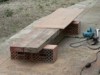
The build has begun!
Finally...
I'm very unsure but had to start once of course, otherwise all that lurking for hours/years would be useless...
Building an eight sided box is not easy, only two hands here and no special equipment.
I wanted to use angled cuts so the bond would be strong and the sheet sides invisible.
Cutting a 22.5° angle with a circular handsaw and a straight edge is challenging.
I don't even have a descend table nor a big garage. But the weather is working with me, predictions are good and I'm at home for two days (vacation days)
Sorry, enough rambling.
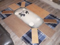
Professional setup and layout before gluing.
I'm getting scared now
Finally...
I'm very unsure but had to start once of course, otherwise all that lurking for hours/years would be useless...
Building an eight sided box is not easy, only two hands here and no special equipment.
I wanted to use angled cuts so the bond would be strong and the sheet sides invisible.
Cutting a 22.5° angle with a circular handsaw and a straight edge is challenging.
I don't even have a descend table nor a big garage. But the weather is working with me, predictions are good and I'm at home for two days (vacation days)
Sorry, enough rambling.
Professional setup
and layout before gluing.I'm getting scared now
Attachments
- Status
- This old topic is closed. If you want to reopen this topic, contact a moderator using the "Report Post" button.
- Home
- Loudspeakers
- Subwoofers
- Pivoting TV-stand/HT-sub/stealth corner