Hello
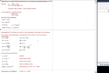
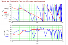
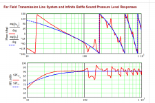
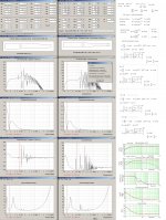
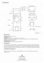
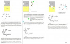
I have a single Dynaudio 30 W100 12" woofer that I'd like to use in a transmission line-type subwoofer. After playing around with the TL design software I've come up with this design. According to the simulation, it has a quite smooth response even without acoustic stuffing and a -6 dB point of approximately 20 Hz.
I'd be glad to receive some opinions and comments about this design.
Attachments
-
 1-definitions.png33.5 KB · Views: 714
 -
 8-systemtimeresponse.png11.9 KB · Views: 70
 -
 7-displacement.png12.7 KB · Views: 69
 -
 6-impedance.png18.1 KB · Views: 68
 -
 5-wooferterminusresponse.png29.9 KB · Views: 666
 -
 4-systemresponse.png25.7 KB · Views: 678
 -
 3-terminusvelocity.png21 KB · Views: 675
 -
 2-acousticimpedance.png22 KB · Views: 686
Last edited:
Upon closer examination of the line geometry the inner volume of the enclosure would be closer to 350 liters, which is way beyond my size constraints. It seems like I would have to go with a sealed enclosure type with ~120..150 liters (if I'm to use this driver).
Hi,
Other options:
b
")
Attachments
Hi,
Other options:
b
Thanks for your suggestion!
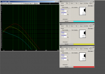
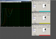
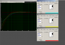
Does your simulation show that it would be possible to attain an f-3 dB of 15 Hz using this driver in some kind of a special enclosure (OD-T-TQWT)?
I also simulated this driver in an ordinary ported enclosure by varying the tuning frequency. The yellow tuning produces a rounded response curve, but nothing like an f-3 dB of 15 Hz.
Attachments


..Does your simulation show that it would be possible to attain an f-3 dB of 15 Hz using this driver in some kind of a special enclosure (OD-T-TQWT)?
I also simulated this driver in an ordinary ported enclosure by varying the tuning frequency. The yellow tuning produces a rounded response curve, but nothing like an f-3 dB of 15 Hz.
Hi d1030180,
Yes I prefer a T-TQWT or TQWP for the very low end. Search my contributions in various thereads I you will probably understand why.
A continuously variable 2nd to 4th order HPF from ~ 10 Hz-40 Hz to protect the driver from over-excursions is IMO handy when listening to demanding music using an relatively low xmax driver like the Dynaudio 30 W100.
b
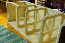
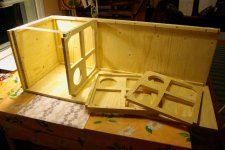
I will build the enclosure from 18 mm plywood and wish to add three horizontal panels and some additional slabs inside the enclosure for bracing.
As the bracing panels will divide the enclosure into four partitions, are there any advantages in cutting three of the horizontal panels into free-flowing "window braces", while making some kind of resistive port into the fourth panel. I have seen this kind of structure in the local loudspeaker manufacturer's subwoofer model seen on this website:
Google Translate
As the (unfortunately quite poorly translated) page mentions:
Harri's design seems to be dividing the airspace V into approximately (1/3)*V for the upper enclosure and (2/3)*V for the lower. Does this kind of enclosure alignment have some advantages when used with woofers with certain T/S parameters (such as the Peerless SLS driver in the commercial design)?
As the bracing panels will divide the enclosure into four partitions, are there any advantages in cutting three of the horizontal panels into free-flowing "window braces", while making some kind of resistive port into the fourth panel. I have seen this kind of structure in the local loudspeaker manufacturer's subwoofer model seen on this website:
Google Translate
As the (unfortunately quite poorly translated) page mentions:
In the schematic drawing, "ylempi välilevy" means the upper horizontal (resistive) bracing panel and "alempi välilevy" the lower one.Construction of the enclosure is closed, but the dual-chamber, a controlled leak in a partition wall.
Housing Principle improve bass response and dynamics control.
Harri's design seems to be dividing the airspace V into approximately (1/3)*V for the upper enclosure and (2/3)*V for the lower. Does this kind of enclosure alignment have some advantages when used with woofers with certain T/S parameters (such as the Peerless SLS driver in the commercial design)?
Attachments
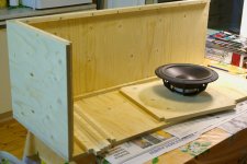
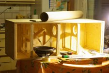
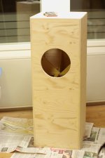
I have been busy with the build and it's progressing nicely. Three of the panels have been attached. I used support sticks, torx screws and plenty of wood glue on every joint, so the enclosure should end up being airtight.
In the end I might have to fix the backside wall by gluing & screwing it in from the outside.
There's not much information available regarding the design of a dual-chamber aperiodic enclosure and the Qts value of the driver is only around average, so I might choose a low-tuned vented alignment for this sub.
Attachments
I certainly hope not! I thought it would be quite OK with many bracing panels & sticks & triangles added inside the enclosure?18 mm wall thichness is too little for a subwoofer of this size.
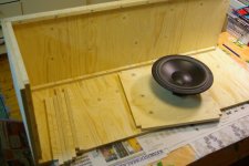
Here is a picture of one bracing panel glued and screwed, I didn't have enough time to finish installing the others on this weekend.
Hopefully I have some time to install the remaining panels next weekend! And also to add some triangular-shaped vertical braces.
Attachments
I certainly hope not! I thought it would be quite OK with many bracing panels & sticks & triangles added inside the enclosure?
Here is a picture of one bracing panel glued and screwed, I didn't have enough time to finish installing the others on this weekend.
Hopefully I have some time to install the remaining panels next weekend! And also to add some triangular-shaped vertical braces.
Hi d1030180,
Agree, Looks to be a well built design..
An late answer for Post#7:
b
Attachments
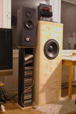
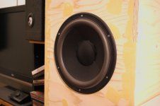
I have recently been testing a sealed prototype of this sub.
The sub integrates nicely with the main speakers after stuffing their ports tightly with cotton wadding. I get the best sound when I set the plate amp's crossover frequency to 40 Hz and volume to around 40 %. With these settings I find its sound very good indeed, at least with music material. Its output is definitely more impressive than the compact 10" subwoofer which I finished building during last summer.
With the port opening closed by a piece of MDF and no enclosure stuffing I measured a resonance peak at 35 Hz. I don't have any way to measure the frequency response, but after testing with some test tracks it seems to extend at least down to 25 Hz. According to the simulation based on the location of the impedance peak, the total Q should be around 0,68..0,70.
The crossover is still a bit high for me and I'm planning to change some components in the filter section to attain a slightly lower adjustment range. Maybe something like 30-100 Hz instead of current 40-160 Hz. I've already modified the filter to get rid of the in-built peaking (+6 dB/40 Hz) second order high-pass filter.
I still need to decide which plate amplifier should I be using with this sub. Currently the enclosure has a slight leak in one of the bottom corners, so I would need to cut a hole anyway to be able to reach all the corners for applying wood glue.
Attachments
Finally had some free time for applying some putty and sanding to smooth out the gaps and small imperfections. The finish won't be perfect as the surface of the wood material itself is not totally straight; however this is not such a big problem for me.
Attachments
- Status
- This old topic is closed. If you want to reopen this topic, contact a moderator using the "Report Post" button.
- Home
- Loudspeakers
- Subwoofers
- Dynaudio 12" transmission line subwoofer