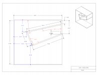
From B&C a 18" woofer horn load plans:
An externally hosted image should be here but it was not working when we last tested it.
An externally hosted image should be here but it was not working when we last tested it.
An externally hosted image should be here but it was not working when we last tested it.
Attachments
-
 SGG_57 leonardo_Pagina_05.jpg181.3 KB · Views: 415
 -
 SGG_57 leonardo_Pagina_01.jpg105.1 KB · Views: 147
 -
 SGG_57 leonardo_Pagina_02.jpg132.2 KB · Views: 154
 -
 SGG_57 leonardo_Pagina_06.jpg170.9 KB · Views: 102
 -
 SGG_57 leonardo_Pagina_09.jpg108.3 KB · Views: 112
 -
 SGG_57 leonardo_Pagina_08.jpg177.8 KB · Views: 133
 -
 SGG_57 leonardo_Pagina_04.jpg174 KB · Views: 130
 -
 SGG_57 leonardo_Pagina_03.jpg197.5 KB · Views: 127
 -
 SGG_57 leonardo_Pagina_07.jpg82.7 KB · Views: 386
TEF abuse =
An externally hosted image should be here but it was not working when we last tested it.
Attachments
Last edited:
Weird because bracing looks adequate down the center of the large panels
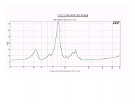
That is curious. The impedance response doesn't lie, but I guess it might be open to misinterpretation 🙂.
Based on my admittedly short experience with building horns, those ripples in the curve (starting from around 62 Hz) and poorly defined upper resonance peak are suggestive of poor bracing. See The Subwoofer DIY Page v1.1 - Projects : Using Impedance Graphs
??????????Weird because bracing looks adequate down the center of the large panels
What do you mean?
Look at the second to last image attachment
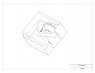
3D view. There is bracing connecting almost every panel. Except the sealed chamber sides around the driver. Theres also a large brace with a handle cutout connecting the sides of the mouth.
Look at the second to last image attachment
3D view. There is bracing connecting almost every panel. Except the sealed chamber sides around the driver. Theres also a large brace with a handle cutout connecting the sides of the mouth.
not important, but something I dont quite understand
why is a 50hz bass horn smaller than a 100hz midbass horn, or close to equal, but only longer ?
is mouth size more important with the upper 100-200hz midbass ?
why is a 50hz bass horn smaller than a 100hz midbass horn, or close to equal, but only longer ?
is mouth size more important with the upper 100-200hz midbass ?
Hi Tinitus
Size is important to all horn-mouth. The Shape only becomes important when the mouth reaches the ¼ wavelength. Therefore large horns with ‘smaller’ than ideal mouth are designed in such way that in groups of four, the combined mouth is more or less square shaped.
¼ WL for 50Hz = 1.7 m
¼ WL for 100 Hz = 0.85 m
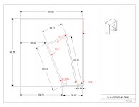
Yes you have the dimensions for the rear chamber.
And Djim, if you made one continuous brace with triangle cutouts that would work better?
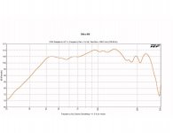
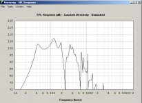
The measured frequency response looks okay, not flat but still not terrible.
And Djim, if you made one continuous brace with triangle cutouts that would work better?
The measured frequency response looks okay, not flat but still not terrible.
Hi mRgSr,
For bass horns you need to connect everything otherwise you will loose more than just 1 or 2dB at max levels. The braces don’t necessarily need to be constructed from one single piece but they do need to be connected to the opposite walls.
Bass horns this large need braces that are supported over the entire length were they connect. In other words, increasing the attachment surface. One misconception is that braces need to be as thick as the panels. Think of a 3 or 4 leg light-bars/trusses. They are stiff by the construction that exists from 3 or 4 strong bars and connected with much smaller enforcement bars. In case of large bass horns I prefer to have two braces, each of 9 mm and with some strategic cut outs to safe weight, than one 19 mm brace.
And Djim, if you made one continuous brace with triangle cutouts that would work better?
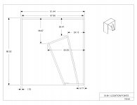
If I would building this, I would be tempted to use two cross-braces instead of one, to push the panel resonance frequencies even higher.
Hi Y'all,
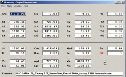
Post #13: "So can this be modeled in HornResp?"
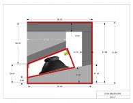
This is my take at it (the numbers/angles do not match exactly, but what else is new?):
Regards,
Post #13: "So can this be modeled in HornResp?"
This is my take at it (the numbers/angles do not match exactly, but what else is new?):
Regards,
Attachments
it would be better if the bracings were conecting 2 sides,with holes cut out.
same weigt in wood ,but far more stiffer.
nevertheless nice effort🙂
edit/oops didnt read page 2😱
same weigt in wood ,but far more stiffer.
nevertheless nice effort🙂
edit/oops didnt read page 2😱
Last edited:
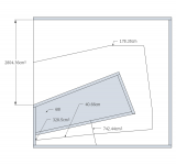
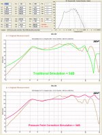
There is an alternative way of simulating this horn. Simulations use fixed points for highest pressure point, at S2. In the real world this isn't correct. For this horn the highest pressure is situated at S1. You can simulate this by putting S2 on the position of S1. Section S1-S2 is therefore no longer in use, which means you need to correct the length between the S-points. The result is that the resonances are now on the correct positions in the frequency range.
Downsides: The impedance is also not longer correct because the driver is still where it was. Above the quarter wavelength frequency of the distance between the 'new' S2 en the old position (in this case 40cm = 214 Hz) the resonances can be inverted.
If this all sounds 'complicated', just look at the HornResponse inputs.
(Thanks to Oliver for the drawings of the horn)
Attachments
- Status
- Not open for further replies.
- Home
- Loudspeakers
- Subwoofers
- 18" B&C WOOFER HORN LOAD