Thanks GM! I definitely prefer working with Titebond vice PL. To bad I don't have a jointer as it would make creating the proper angles a piece of cake.
A jointer is a nice tool, but probably a little over kill for your application. You should be able to get it with a circular saw with a little trial and error. Just make sure and clamp down a straight edge to keep everything straight. Alternately you could cut everything at 90 degrees, then just shave a couple of degrees off with a block plane. You can find them pretty cheap on ebay: Stanley 110 Block Plane w Original Box Made in England Spectacular Condition | eBay
Hi NWCgrad,
I print out an angle, and use it as a measurement tool to set up the blade on the table saw (or a circular saw). Just folding along the lines gives a simple tool.
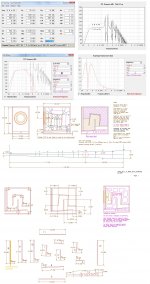
By now you should have the final drawings for MOD3, and hopefully they are not full of errors. The final angle ended up @ 3.15 degrees, obviously that's just on paper; just like the dimensions to .001" thats just because it's easier that way in AutoCAD.
Regards,
I print out an angle, and use it as a measurement tool to set up the blade on the table saw (or a circular saw). Just folding along the lines gives a simple tool.
By now you should have the final drawings for MOD3, and hopefully they are not full of errors. The final angle ended up @ 3.15 degrees, obviously that's just on paper; just like the dimensions to .001" thats just because it's easier that way in AutoCAD.
Regards,
Attachments
Hi NWCgrad,
I print out an angle, and use it as a measurement tool to set up the blade on the table saw (or a circular saw). Just folding along the lines gives a simple tool.
By now you should have the final drawings for MOD3, and hopefully they are not full of errors. The final angle ended up @ 3.15 degrees, obviously that's just on paper; just like the dimensions to .001" thats just because it's easier that way in AutoCAD.
Regards,
Thanks Oliver...I do not see any errors in MOD3. Will get them on the thread sometime today.
I print out an angle, and use it as a measurement tool to set up the blade on the table saw (or a circular saw). Just folding along the lines gives a simple tool.
FWIW, I use an adjustable drafting triangle: https://www.google.com/search?q=adj...j7&sourceid=chrome&espv=210&es_sm=93&ie=UTF-8
GM
A jointer is a nice tool, but probably a little over kill for your application. You should be able to get it with a circular saw with a little trial and error. Just make sure and clamp down a straight edge to keep everything straight. Alternately you could cut everything at 90 degrees, then just shave a couple of degrees off with a block plane. You can find them pretty cheap on ebay: Stanley 110 Block Plane w Original Box Made in England Spectacular Condition | eBay
Thanks I have a block plane...easy to screw up if not carefull.
MOD-3 Plans
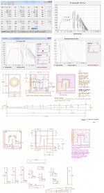
Here are tb46's MOD-3 Hornresp input and enclosure design. I wanted the enclosure to be as small as possible and still have a -3 dB point of ~20 Hz. Since these two subs will be for music this should be sufficient.
Thanks again Oliver (and Bjorno) for all the assistance on this build. Its been a long strange trip.
Is polyfill okay for the stuffing or does it need to be some expensive, hard to find material?
Attachments
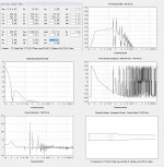
In case anyone wants more output (and who doesn't), here is Oliver's final design with the TC Sounds Epic 12 driver. It has much more Xmax than the Eminence, and as a result can be driven with 725 W vice 350 W to reach Xmax. Both require an HPF at 19 Hz to prevent runaway cone excursion below tuning (duh!).
Looks like a 5 dB increase in output. Nice, if I didn't already own the LAB-12 I would go with the Epic's. Perhaps a future purchase.
Looks like a 5 dB increase in output. Nice, if I didn't already own the LAB-12 I would go with the Epic's. Perhaps a future purchase.
Attachments
Hi NWCgrad,
In your nice compilation of the drawings (Post #267) there is a board missing in the exploded view, board #5 (it's the same as #11). What program did you use to put that together?
I agree, the TC Sounds Epic 12 looks like a great driver. And, at least on paper, it seems to work in all kinds of enclosures.
Regards,
Last edited:
Hi NWCgrad,
In your nice compilation of the drawings (Post #267) there is a board missing in the exploded view, board #5 (it's the same as #11). What program did you use to put that together?
I agree, the TC Sounds Epic 12 looks like a great driver. And, at least on paper, it seems to work in all kinds of enclosures.
Regards,
Oops! Fixed and reposting.
I used the Microsoft Snipping Tool (Win 7) to cut from your PDF into Paint. I then move things around and crop to final size saving as a JPEG (or other file) so I can post as an image.
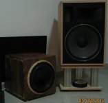
The external baffle will be made from the sealed sub boxes I had made in Cambodia. It is some sort of hardwood. Doing so to add some visual appeal and to salvage the poorly made boxes (at $50/pair for wood and labor one cannot be to picky especially when considered they were made by a lady that has absolutely no access to power tools).
Attachments
Last edited:
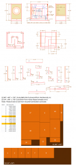
Trying to make finalized cutsheet. How much can I deviate from the CAD dimensions? CAD is three digit accuracy but there is no way I can make cuts to 1/64" accuracy. I assume 1/8" accuracy is sufficent but I don't kniw for sure and I don't want to mess up Oliver's hard work on this design.
Right now I am leaning towards primarily using real Baltic Birch 13-ply.
Right now I am leaning towards primarily using real Baltic Birch 13-ply.
Here is all the data for the enclosures - modified to add a second rear panel and an access panel for adding/removing stuffing from the closed end of the enclosure. Will require the purchase of 2 sheets of 60 in x 60 in Baltic Birch.
Over the weekend I plan to go through the entire thread and post links/post #'s for the various designs on page 1.
Over the weekend I plan to go through the entire thread and post links/post #'s for the various designs on page 1.
Attachments
Hi NWCgrad,
Just saw your question from Post #272: "How much can I deviate from the CAD dimensions?..."
As to the general question of deviating from the CAD dimensions, 1/64th of an inch is 0.015625, and 1/64th sounds like a good value to shoot for when marking, and placing the 14.562" boards on the side board. If you shoot for that you'll probably stay within +- 1/16" (.0625), and that should not affect the performance of the enclosure.
My recommendation would be to use cleats (e.g.: 3/4" x 3/4") to mount the original back panel, and to forget about doubling up on it; that way you can make the whole back panel removable, and you can make up for the small change in cross-section @ #1 by cutting a little off board #6. The stub from S1 to the upper right hand corner should be very forgiving as far as the exact cross-section is concerned, und you can modify the response w/ stuffing density. Also, I don't think, that there is any good reason against using MDF for some-or all-of the internal baffles. Either way should work just fine. Do add some center dividers/stiffeners.
Regards,
")
Which SAE Felt specification is optimal for lining the transmission line?
I am looking at SAE 3 (0.25" thick) as its a bit cheaper than SAE 1 and still is spec'ed as outstanding vibration absorption. I assume the greater the vibration absorption the better, but that is just a reasoned guess.
I am looking at SAE 3 (0.25" thick) as its a bit cheaper than SAE 1 and still is spec'ed as outstanding vibration absorption. I assume the greater the vibration absorption the better, but that is just a reasoned guess.
- Status
- This old topic is closed. If you want to reopen this topic, contact a moderator using the "Report Post" button.
- Home
- Loudspeakers
- Subwoofers
- Lab 12 Based Offset Driver - Mass Loaded - Transmission Line (OD-ML-TL) Design by Bj