Hi All,
I've a somewhat random driver that seems to be begging for a home to live in. I don't seem to be able to find any specs for it at all, so it's a complete mystery as to parameters for a viable design.
I found Woofer & Subwoofer Thiele-Small Parameter Extraction but I've not absorbed it as yet; are there any other methodologies I should be aware of?
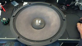
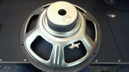
The driver is a "toa bst-126" and has a stated impedance of 8 ohm. Size of the radiating surface seems to be about 310mm (the whole unit is 15")
I figure I'll build some kind of home for it, but I'm unsure what would be the best way of going about it. Any suggestions? I'm moderately competent in woodworking and sourcing 17mm structural ply as a materiel is fairly easy. I also have a few decent sized bits of 25mm MDF about as well...
I guess the next steps are determining the parameters of the driver somehow, and then deciding on sealed/vented box or some sort of horn arrangement to build for it. I live in a fairly small house so an insanely large enclosure isn't viable, but I'm happy to hear the more outlandish suggestions for enclosure options!
I've a somewhat random driver that seems to be begging for a home to live in. I don't seem to be able to find any specs for it at all, so it's a complete mystery as to parameters for a viable design.
I found Woofer & Subwoofer Thiele-Small Parameter Extraction but I've not absorbed it as yet; are there any other methodologies I should be aware of?
The driver is a "toa bst-126" and has a stated impedance of 8 ohm. Size of the radiating surface seems to be about 310mm (the whole unit is 15")
I figure I'll build some kind of home for it, but I'm unsure what would be the best way of going about it. Any suggestions? I'm moderately competent in woodworking and sourcing 17mm structural ply as a materiel is fairly easy. I also have a few decent sized bits of 25mm MDF about as well...
I guess the next steps are determining the parameters of the driver somehow, and then deciding on sealed/vented box or some sort of horn arrangement to build for it. I live in a fairly small house so an insanely large enclosure isn't viable, but I'm happy to hear the more outlandish suggestions for enclosure options!
Attachments
Last edited:
I'll do it this way...
Measuring Loudspeaker Driver Parameters
Geez theres a lot of good data on his site...")
Measuring Loudspeaker Driver Parameters
Geez theres a lot of good data on his site...
As a loudspeaker engineer, my pretty educated guess is that looking at the construction and the size of the magnet, the Q is probably high and it needs a large box to not sound boomy.
You could try
Customer Support
but I wonder, even if you get information, if it would be very accurate.
By the way, different methods of measuring parameters will give different and valid results. The "parameters" are an approximation, a model, and they vary according to the drive level.
You could try
Customer Support
but I wonder, even if you get information, if it would be very accurate.
By the way, different methods of measuring parameters will give different and valid results. The "parameters" are an approximation, a model, and they vary according to the drive level.
I found the BST-142 in the TOA SLB subwoofer. If model numbers are anything to go by it would seem the BST-126 is the predecessor, maybe the sensitivity and power rating is similar, but there is no way to tell.
http://www.toaelectronics.com/disc/manuals/SDB_SLB.pdf
Edit:
Also found what seems like an auction for the BST-126 here:
http://yackdb.s138.xrea.com/auview.php?m=BST-126|TOA
Edit2:
I would just toss together a H frame for the heck of it, might work excellent.
http://www.toaelectronics.com/disc/manuals/SDB_SLB.pdf
Edit:
Also found what seems like an auction for the BST-126 here:
http://yackdb.s138.xrea.com/auview.php?m=BST-126|TOA
Edit2:
I would just toss together a H frame for the heck of it, might work excellent.
Last edited:
Hmmmm...
15" subwoofer is always gonna need a big box, unless you throw away a lot of efficiency and go for a small sealed cabinet with Linkwitz Transform.
Or, as suggested above, try a H-frame. I'm not keen on them myself, but its a surefire way of getting something out of an unknown driver.
Chris
15" subwoofer is always gonna need a big box, unless you throw away a lot of efficiency and go for a small sealed cabinet with Linkwitz Transform.
Or, as suggested above, try a H-frame. I'm not keen on them myself, but its a surefire way of getting something out of an unknown driver.
Chris
Cheers for the input everyone
I gave the process detailed in Rod Elliotts site a whirl, but (and I quote)
"First, measure the resonant frequency. Adjust the frequency until the voltage across the resistor reaches a null (minimum level). Without changing anything, carefully measure the frequency and voltage across the resistor ..."
...was a wash. I was started at a 200Hz tone and varied it about more or less randomly, and the voltage over the 10R resistor as measured by my multimeter never seemed to hit a 'low' as such; nor settle down at all really.
I take it from head_unit's comments that the parameters are pretty variable anyway, so would end up a rough approximation of the ideal values.
I guess popping it into a H frame is easy enough to just do and see how it goes. I'll get to reading and see what I come up with. Thanks for the commentary and suggestions!
Last edited:
considering a sonotube style construction...
http://www.passdiy.com/pdf/el-pipe-o.pdf
I like parties.
Upon re-reading I realize that little bon-mot may need explanation - read the article and it'll make sense.
Now to find a local supplier of sonotube materiel... That said I've only an 8ft ceiling here
http://www.passdiy.com/pdf/el-pipe-o.pdf
I like parties.
Upon re-reading I realize that little bon-mot may need explanation - read the article and it'll make sense.
Now to find a local supplier of sonotube materiel... That said I've only an 8ft ceiling here
Last edited:
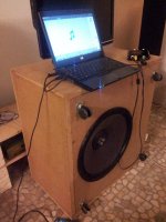
Well I've reconsidered my approach and dug out the original planned enclosure for this woofer. It's about 90L of volume and sealed; the materiel used was 1 inch MDF. I figure as I have it I may as well test it out and then move to a H frame after if needs be.
Currently reading up on Linkwitz transform....
Currently reading up on Linkwitz transform....
So I've thrown it into a sealed enclosure of internal volume of (in mm) 635*335*500 and given it a bit of a test. Seems like the -3db point is about 40Hz (completely subjective hearing judgement). Lobbed a couple of pillows in as well and she seems a little better again...
So it seems the next step is a linkwitz transform circuit, some sort of unbalanced to balanced converter for a bridged amp setup. I've a SCULD2 amp I'd be happy to gut for this (http://www.diyaudio.com/forums/solid-state/134221-silicon-chip-200watt-ld-amplifier.html) and have had a quick look at Linkwitz Transform Subwoofer Equaliser and Balanced Transmitter and Receiver II and these seem to be a potential path forward.
I have a couple of questions though.
1) bridging amp modules - is this necessary? I have em and I'm happy to sacrifice them to sub wooferage use, but I guess removing any kind of LF roll off may be in order...
2) crossover details. I guess I need something that has a variable freq cutoff to tune it in initially and then I can look at an active solution as a permanent solution once the freq is determined.
3) linkwitz transform circuit - where does it go? I guess in the end I'll be looking at
source -> preamp -> variable freq low pass crossover -> (A or B)
A> amp -> normal speakers
B> linkwitz transform -> bridged amp -> subwoofer driver
Sound about right?
I suppose more clearly, I mean can the mini dsp unit act as a crossover, and then perform a linkwitz transform on the low end output, and invert the phase of one of those low end outputs?
Yes, plus time correction and parametric eq.
Progress!
So - I went and built me a 250W Class D amp (with something a little gruntier to come) and scored a minidsp-inabox second hand for a fair price...
And now I'm having a little bit of a play with the whole lashup! I just wandered outside to make sure the house wasn't sounding like a nightclub at 11pm on a thursday.
I've manually entered an eq that kind of replicates a linkwitz transform roughly - seems I need to learn all the speaker language now, so I can program in a proper linkwitz transform into the minidsp for the components i have here. Qts, Qs, Fo, Rsvp, etc etc
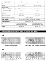
In terms of driver specs/data all I really have to go on is the below graph from the datasheet mentioned in one of the previous posts (relevant bits below), and obviously thats for a completely different setup. Any suggestions for the relevant parameters anyone?
Well, I'll keep experimenting!
So - I went and built me a 250W Class D amp (with something a little gruntier to come) and scored a minidsp-inabox second hand for a fair price...
And now I'm having a little bit of a play with the whole lashup! I just wandered outside to make sure the house wasn't sounding like a nightclub at 11pm on a thursday.
I've manually entered an eq that kind of replicates a linkwitz transform roughly - seems I need to learn all the speaker language now, so I can program in a proper linkwitz transform into the minidsp for the components i have here. Qts, Qs, Fo, Rsvp, etc etc
In terms of driver specs/data all I really have to go on is the below graph from the datasheet mentioned in one of the previous posts (relevant bits below), and obviously thats for a completely different setup. Any suggestions for the relevant parameters anyone?
Well, I'll keep experimenting!
Attachments
Last edited:
- Status
- This old topic is closed. If you want to reopen this topic, contact a moderator using the "Report Post" button.
- Home
- Loudspeakers
- Subwoofers
- Woofer Driver Needs a Home Built for it