Hi all
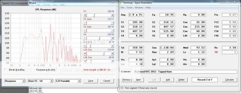
I found out about tapped horns a few months ago, and straight away I thought I had to try one.I set about learning Hornsrep, with the help of related posts on this and other forums, put together what I think is correct.
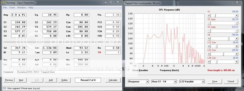
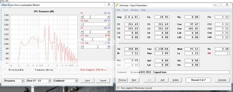
Im at the point now where I need to ask the "old hands" for some guidance.As you can see from the pic below the response looks like the top of a castle wall, and nothing I seem to do will flatten it out. I have come to the conclusion the Sub is just rubbish (kenwood KFC-W2512 ) I know its a car sub, but as this is just a learning experience I thought why not.
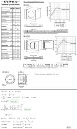
So the specs of the sub are as follows for anyone who is willing to take the time to lend a hand.
fs = 44Hz ( I see its listed as 48 Hz on other documentation , Sigh . )
sd = 350
Qms = 14.047
Qes = 1.821
Qts = 1.612
Xmax = 13 mm
BL = 7.5
Le = 1.15mH
Re = 3.5
Z = 4
Vas = 19.7 L
I'm not even sure if my Hornsrep data is correct, so go easy on me
I found out about tapped horns a few months ago, and straight away I thought I had to try one.I set about learning Hornsrep, with the help of related posts on this and other forums, put together what I think is correct.
Im at the point now where I need to ask the "old hands" for some guidance.As you can see from the pic below the response looks like the top of a castle wall, and nothing I seem to do will flatten it out. I have come to the conclusion the Sub is just rubbish (kenwood KFC-W2512 ) I know its a car sub, but as this is just a learning experience I thought why not.
So the specs of the sub are as follows for anyone who is willing to take the time to lend a hand.
fs = 44Hz ( I see its listed as 48 Hz on other documentation , Sigh . )
sd = 350
Qms = 14.047
Qes = 1.821
Qts = 1.612
Xmax = 13 mm
BL = 7.5
Le = 1.15mH
Re = 3.5
Z = 4
Vas = 19.7 L
I'm not even sure if my Hornsrep data is correct, so go easy on me
Last edited:
Hi, like you I'm on the learning curve. I just put your sub into a T-TQWT that another member designed for me and got a similar bump in the 40-60Hz region too, so tried it in a tapped horn design too-also looks like a snowboarders wet dream.
Please double check your values-when I entered in the values and asked HR to calculate others I ended up with different MMD...
Please double check your values-when I entered in the values and asked HR to calculate others I ended up with different MMD...
Yeah, the specs calculate a usable max flat BW of ~43.7-52.7 Hz, so a 'one note' wonder. It has enough Xmax to mass load it to a lower Fs/higher Qts that would at least allow a lower 'one note' .
GM
edit: That said, try a basic TL tuned to ~Fs/Qts = 29.78 Hz in ~2.5 ft^3 net. Once stuffed it should be much flatter/extended. If it looks OK to you, then try adjusting it for tapped variants [TTL, TTQWT].
. GM
edit: That said, try a basic TL tuned to ~Fs/Qts = 29.78 Hz in ~2.5 ft^3 net. Once stuffed it should be much flatter/extended. If it looks OK to you, then try adjusting it for tapped variants [TTL, TTQWT].
Last edited:
A response curve falling within +/- 3 dB is considered good..
As you can see from the pic below the response looks like the top of a castle wall, and nothing I seem to do will flatten it out. I have come to the conclusion the Sub is just rubbish .
HornResp tends to exaggerate dips and peaks.
Your response chart is within +/- 2.5 dB in the pass band, hardly "rubbish".
If the design as built conforms to the chart, it won't sound bad, and a little EQ could smooth out the "castle" which is far less a problem than room modes (often +/- 6 dB or more) will be.
I just built a sub that has a -6 dB hole that would be the reciprocal of a room peak...
Art
Ya that graph looks alright, 2 full octaves, unless you chop off above 80. Still 35-80 is decent. Perhaps you could post the spl response? Lots of xmax to play with.
I must say that qts spec is insane, never seen over 1 qts!
maybe wack the box out with a single fold and play with it.
also the woofer tester from parts express, when its in stock, should help you out now your across the event horizon of the black hole known as diy subwoofer design and building.
I must say that qts spec is insane, never seen over 1 qts!
maybe wack the box out with a single fold and play with it.
also the woofer tester from parts express, when its in stock, should help you out now your across the event horizon of the black hole known as diy subwoofer design and building.
Please double check your values-when I entered in the values and asked HR to calculate others I ended up with different MMD...
Mmm, Just did check the numbers, you were right, Since the MMD was given I put that in and looked at the figures that were calculated, this put everything out,but not by much.This means that something on the listed figures is not 100% correct.
Most errors were at the first and second decimal, it also dropped the fs by 1.4 Hz, I don't think the discrepancies will be to detrimental, as this is my first build ? will they ?
. Perhaps you could post the spl response?
also the woofer tester from parts express, when its in stock, should help you out now your across the event horizon of the black hole known as diy subwoofer design and building.
Is the graph above not the SPL Response ? ( sorry I'm learning)
The tester would be nice, shipping to South Africa is rather pricey, but on the cards for the future
Is the graph above not the SPL Response ? ( sorry I'm learning)
The tester would be nice, shipping to South Africa is rather pricey, but on the cards for the future
Yup, it is.
I had one shipped to the UK, ended up about the same price in £ as the unit was in $-I did wait until the Thanksgiving sale so was $89.99 IIRC
Yeah, the specs calculate a usable max flat BW of ~43.7-52.7 Hz, so a 'one note' wonder. It has enough Xmax to mass load it to a lower Fs/higher Qts that would at least allow a lower 'one note'
GM
edit: That said, try a basic TL tuned to ~Fs/Qts = 29.78 Hz in ~2.5 ft^3 net. Once stuffed it should be much flatter/extended. If it looks OK to you, then try adjusting it for tapped variants [TTL, TTQWT].
Right, So I did a few of calculations based on these figures, 29.78 Hz equates to a line length of roughly 285 cm, based on the net volume of 71 Liters (2.5 Cubic feet) I came up with the following, which simulated similarly as a "horn", and " Vented " enclosures ( seeing if I could replicate the result via a different means, Isn't learning fun)
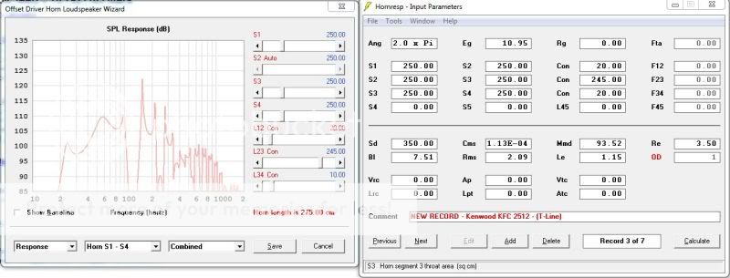
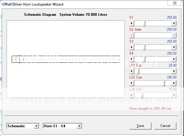
Schematic is as follows ( Please someone point out if I'm doing something wrong , or stupid.)
Judging by the results here I would guess this TL is not really an option. ( time for some more playing).
I don't know if I would personally put the effort of a TL build into a driver with such a sloppy motor. Some people may disagree but in my experience, very high Qts, while easy on amplification, also means that there is very little amplifier control over the movement of the motor. Very high Qts means very high impedance peak means a lot of the cone motion is powering along under the effects of resonance rather than amplifier control. Expect high non-linear distortion, and, as you are seeing in simulations, a difficult time getting much linearity in response as well. An infinite baffle loading is the best way to try to get some reasonable behavior out of it IMO. Just build a box that opens to a crawl space or something.
..net volume of 71 Liters (2.5 Cubic feet) I came up with the following, which simulated similarly as a "horn", and " Vented " enclosures..
That's a good start..
..( seeing if I could replicate the result via a different means, Isn't learning fun)..
Learning is fun so is IMO DIY too..
Schematic is as follows ( Please someone point out if I'm doing something wrong , or stupid.)
Nothing wrong but more in depth analyzing of what you could do is IMO needed..
[/QUOTJudging by the results here I would guess this TL is not really an option. ( time for some more playing).
A TL could be designed too but starting with that kind of driver is not that easy.
Read the following :2cent: of my investigations:
To tame your Car driver with a 'built in 'one note feature into a sub that will permit 'music' use :
First: read this thread:
http://www.diyaudio.com/forums/subwoofers/107095-did-i-see-thread-linkwitz-transform-reflex-2.html
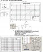
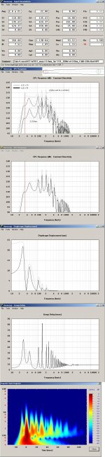
Calculate the f-3dB point and equivalent Qt value for a ~100L box (Picture 1) then enter the data into:
http://www.trueaudio.com/downloads/linkxfrm.xls
That is: The f-3dB= 35.9 Hz = f(0) and Qt= 1.762 = Q(0) then target f(p) to 12 Hz and Q(p) to 0.6.
Add a Bw 12 dB/octave HPF at 20 Hz in front of the LT filter. Only a ~5 dB Amplitude-loss = ~56%= ~3.16 dB Power-loss is expected for this arrangement.(Picture 2)
f-3 dB for the system is ~23 Hz if in a 100L closed box, You might stop here if a closed LT box suits your initial requirement of a sub.
If you want to extend the FR further:
The resulting FR from the Qt of = 0.6 the f-3dB can be extended down a bit if adding a BP function = a port tuned below 23 Hz.
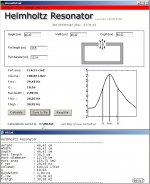
To calculate a 'Helmholtz port for the 100L box use the Helmholtz Resonator calculator found here:
http://www.mh-audio.nl/user/acoustic calculator.asp
Now enter Height= 46.42 cm;Width= 46.42 cm and Depth= 46.42 cm for the 100L box, add a port= diameter= 12.19 cm and Length = >= 30.5 cm.
Read that the port resonance is ~29.5 Hz or below.(Picture 3)
If moving over to HR:
Hornresp
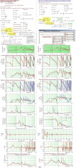
Enter your driver data into HR and let HR, do a consistency check of the fundamental T/S data,then enter:
S1= 2155;S2= 2155;S3= 2155;S4= 117 and S5= 117.L12=46,4:L23=0,01:L34=0,01 and L45=30,5.
Set Re= 1.2 Ohm, Check TS data by double clicking on Sd that only Qts has changed,....here to ~0.6.
This operation is equivalent to adding of negative resistance thus lowering of Qts only. Remember that when stuffing the entire box constituting a driver with a Qts > 0.5, is ~appearing as Qt of~ 0.6 after the LT filter and the preceding mandatory HPF.
Click the calculate button for FR and so on..
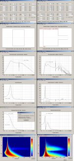
Looking at the FR you will note that the low end will severely peak when Re is set to 1.2 ohm but would even be more severe if you test with the ordinary 3.5 Ohm instead. (Picture 4)
IME, You can ignore the peak at the low end if it's less than 3 dB but for this case the ways to smooth out this peak are
1. Filtering(or use an EQ) or
2. Stuff the entire box until a smooth response ocurrs, or
3. IMO best if turned into an aperiodically stuffed OD-TL or a TH using damping material. (Picture: 5 and 6).
b
Attachments
-
 Keenwood-KFC-W2512_1.JPG167.7 KB · Views: 246
 -
 Keenwood-KFC-W2512_LT_2.JPG365.5 KB · Views: 233
 -
 !00L_Keenwood-KFC-W2512_helmholtz-box_3.JPG74.8 KB · Views: 231
 -
 Keenwood-KFC-W2512_LT_closed_ported-box_4.JPG432.6 KB · Views: 77
 -
 Keenwood-KFC-W2512_OD-TL_Without-LT_With_5.JPG768.5 KB · Views: 71
 -
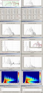 Keenwood-KFC-W2512_Stuffed_TH~73L_LT_6.JPG517.1 KB · Views: 64
Last edited:
Wow bjorno, On another level sir. Thank you for that huge effort.
I feel like iv wondered out into the deep end here.
So after a few cups of coffee, many threads and even more Google searches, Im starting to get to grips with what is going on here, A normal sane person would ditch this sub, and find something more suitable, but the amount I have learned this morning is phenomenal. so que the questions
I see that the models that you have put together(last Pic) were all roughly 70 Liters, is there something about that volume that is optimum ?
Is the model that I provided in my first post not easier to work with ? would the response " flatten out " if I added stuffing ? ( I'm concerned I might be taking on to much with the addition of a LT filter )
The LT filer really caught my attention,esp that thread you pointed me to,I did a bit more reading with regards to power and speaker sensitivity, basically cautioning against low sensitivity speakers and LT filters. This old thing is only 83 dB, is it viable to use a LT filter here ? (Not questioning you, Just trying to understand.)
I see that you selected f(p) as 12Hz for the LT filter ? why so low, what effect would say 20Hz have?
Is changing the Le to 1.2 just to " trick " hornsrep into producing a figure of 0.6 for Qts so that we can factor the LT filter into the simulations ?
I am very tempted to put the LT filter together because of how it makes the sub Sim, much smaller enclosure, and much flatter. My only concern is that this is meant to be an introduction , and I'm concerned I might be taking on to much.
I feel like iv wondered out into the deep end here.
So after a few cups of coffee, many threads and even more Google searches, Im starting to get to grips with what is going on here, A normal sane person would ditch this sub, and find something more suitable, but the amount I have learned this morning is phenomenal. so que the questions
I see that the models that you have put together(last Pic) were all roughly 70 Liters, is there something about that volume that is optimum ?
Is the model that I provided in my first post not easier to work with ? would the response " flatten out " if I added stuffing ? ( I'm concerned I might be taking on to much with the addition of a LT filter )
The LT filer really caught my attention,esp that thread you pointed me to,I did a bit more reading with regards to power and speaker sensitivity, basically cautioning against low sensitivity speakers and LT filters. This old thing is only 83 dB, is it viable to use a LT filter here ? (Not questioning you, Just trying to understand.)
I see that you selected f(p) as 12Hz for the LT filter ? why so low, what effect would say 20Hz have?
Is changing the Le to 1.2 just to " trick " hornsrep into producing a figure of 0.6 for Qts so that we can factor the LT filter into the simulations ?
I am very tempted to put the LT filter together because of how it makes the sub Sim, much smaller enclosure, and much flatter. My only concern is that this is meant to be an introduction
, and I'm concerned I might be taking on to much.I see that the models that you have put together(last Pic) were all roughly 70 Liters, is there something about that volume that is optimum ?
No, Practically it would be difficult to accommodate the driver and the need for suitable port area if using a smaller volume.
Is the model that I provided in my first post not easier to work with ? would the response " flatten out " if I added stuffing ? ( I'm concerned I might be taking on to much with the addition of a LT filter )
Yes you can flatten the response but only in case a very large long enclosure is chosen. Diminishing returns are easily being hit.
The LT filer really caught my attention,esp that thread you pointed me to,I did a bit more reading with regards to power and speaker sensitivity, basically cautioning against low sensitivity speakers and LT filters. This old thing is only 83 dB, is it viable to use a LT filter here ? (Not questioning you, Just trying to understand.)
In the DIY world you make the decisions if it's worth while.
I see that you selected f(p) as 12Hz for the LT filter ? why so low, what effect would say 20Hz have?
If you just lowering the system Q: Due to the high fs the response -3dB would then be pushed higher up in frequency. Then it's all about to get the LT circuit to work properly whilst target a new Q that don't need an LT gain > 20 dB.
Is changing the Le to 1.2 just to " trick " hornsrep into producing a figure of 0.6 for Qts so that we can factor the LT filter into the simulations ?
Yes it's a trick (In MJK:s program this possibility is built in).
I am very tempted to put the LT filter together because of how it makes the sub Sim, much smaller enclosure, and much flatter. My only concern is that this is meant to be an introduction , and I'm concerned I might be taking on to much.
You could use an advanced parametric EQ and a HPF instead, the system result would be about equal.
Though I don't recommend this shortcut because of the needed subLT gain(9 times) of near 20 dB that effectively will be reduced to about 5 dB due to the HPF.
Thus the EQ would probably be working at its extreme ability without any gain margin.
There is also another dangerous situation that can occur:
The attempt to fix the in room system FR at the same time, especially when trying to fix a FR dip( consuming the excursion margin) this is IMO disastrous.
If altering the EQ to flatten out Room response: This will also dent the onset response from the sub,i.e. (normally the TH pre-pulse=) the direct unobstructed wave-launch from the sub will not be heard reproduced but instead produced (= not Hi-Fi).
Use more subs instead if you have FR issues with stationary LF sounds.
b
Attachments
Last edited:
......Isn't learning fun)
Judging by the results here I would guess this TL is not really an option.
It is for me.
Like most things, it depends. Coming from an era of acoustic solutions for acoustic problems, I’ve no hands on experience with using a LRT to modify a driver’s response, so haven’t compared the two. Still, I like high Qts drivers for TL loading, having used up to 2.45 Qts with sonics good enough for folks not to believe the specs.
Offsetting the driver some more smoothes it out further and damping will both finish it up plus improve its effective Qts, though this must be modeled using other software. The main thing though, does the driver’s specs meet the performance wants/needs for the app?
Regardless, the general goal of a basic TL is to get a ~IB response except with better damping in less bulk, which this alignment does and I’m guessing that it will perform better overall than the TH even if heavily damped unless severely limited with a low XO point.
Anyway, load the HR sim to see how the two compare with the understanding that the MJK software has proven to be quite accurate overall if polyfil stuffing is used, which is 0.8 lbs/ft^3 in this case. Being old school, I would just line it with 1” acoustic fiberglass insulation, which would let it be a bit livelier sounding.
GM
Attachments
It is for me.
Anyway, load the HR sim to see how the two compare with the understanding that the MJK software has proven to be quite accurate overall if polyfil stuffing is used, which is 0.8 lbs/ft^3 in this case. Being old school, I would just line it with 1” acoustic fiberglass insulation, which would let it be a bit livelier sounding.
GM
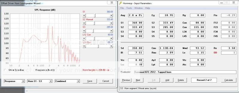
Right, So I got cracking and put together some sims, first off the .TXT you sent( Thanks)
with a bit of playing, adding a small tapper I got to this, only marginally flatter at the low end, but I managed to reduce the line length at the expense of extension. Im happy with it there at about 26-27 Hz (stuffing will drop this wont it ?, If so , I might even cut the length down a bit more.)
The interesting thing about this though, is that I added the LT filter ( I think ) to reduce the Qts to 0.7 with the exact same enclosure, and got this
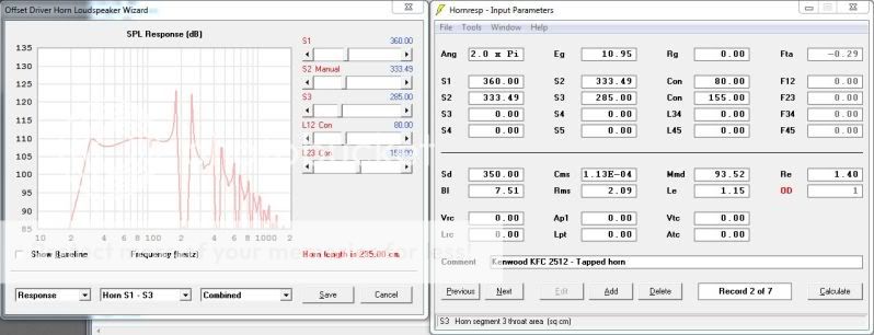
Now, all I did was drop the value of Re to 1.4 to produce the effect of the LT filter ( Im not sure if this is all that needs to be considered, or if its even right at all )
Its looking really good now, considering I can build this, without the LT filter, use it and when I feel brave enough, add it to the mix without changing the enclosure. ( Im really thinking this is where Ill go.because of the flexibility, and the size is 30 odd liters smaller than the TH )
And Just for comparison the TH I put together, Note that all of these are sim'd at 30 Rms
Thanks for all the Input from the members here.
You’re welcome!
Right, reducing Qts only reduces CSA down to ~33.43”^2/~2.13 ft^3 net, so leaving it as is just increases the amount of stuffing required for probably at most an audibly minor in the driver’s upper mids response, so in the case of a woofer it would be rolled off to insignificance by the XO.
I’ve never used a LRT to alter driver properties, but John Murphy [True Audio] did the original Excel calculator back in 1999 for the DIY community and when I asked him if it could be used for, or adapted, to vented alignments, he could see no way to make it work and just noticed that none of its updates includes vented, so am extremely skeptical for now: TA Speaker Topics - Designing a Linkwitz Transform
Yeah, I prefer TQWT loading for many drivers [inverse tapered TL]. Here’s yours compared to the basic TL I posted showing the TQWT’s marginally higher gain BW and the slightly increased 3rd harmonic dip [1st actually showing] due to the taper and larger terminus:
GM
Attachments
![Kenwood KFC-W2512 TQWT [Zubs] comparison.gif](/community/data/attachments/238/238859-700e34fa98774f59f59b7c50735f117e.jpg)
Thanks for the Input on the TL design.
A few questions about the TQWT, and TL designs you put into the Mathcad sheet.
How much Stuffing is in the line for the models you provided ? and where about in the line ? Iv read it really varies according to the ear.
would you regards the TQWT as modeled here, as a decent build ?
Would you recommend the terminus be as near to the driver as possible on exit of the enclosure, as I noticed some variations in Hornsrep.
I really think this is where Ill be going with this build, then a TH with a better suited driver at a later stage ( probably 2 smaller drivers )
Thanks for the help.
Greets!
You’re welcome!
As I noted, 0.8 lbs/ft^3, so for example: 2.5 ft^3 net Vb = 2.5*0.8 = 2 lbs = 32 oz of loose polyfil since it’s the only stuffing material MJK has tested. Consider it just a starting point though since enough folks have stuffed per the sim and have wound up either removing some of it or concentrating it at the closed end same as I do since what they apparently want to hear can be quite a bit livelier [technically distorted] than what a smooth sim produces.
I used the software’s default stuffing allocation; it’s evenly distributed along the entire length of the line since from experience I know it’s dense enough to not settle much.
Define ‘decent’. I mean it has a near identical frequency response as an IB except much more highly damped at Fs in only about 1/100 the cab size and like sealed, it’s more tolerant to driver spec variance and tube friendly compared to a typical vented alignment, so seems pretty decent to me.
Of course what matters is how well it will blend with your room’s modes and in general, it’s relatively high F3/low F10 fits a fairly wide range of rooms assuming it’s not so cluttered to severely limit experimentation/final positioning. Otherwise, that’s what digital EQ is for.
That, or increase acoustical damping by increasing path-length. Simmed is the same ~2.5 ft^3/0.8 lbs/ft^3 stuffing density in a ~175” long line.
The software I used assumes the driver is centered in the terminus, but the WLs involved are large enough that as long as they’re on the same baffle it won’t change its cab loading BW since any path-length difference will be small in comparison.
For other configurations you’ll have to use HR and guesstimate how it will change the MathCad sims, but unless it’s on the rear and the speaker is well away from a reflective boundary, it probably won’t be enough to matter unless you use a very high XO point due to how well damped its output will be.
Note that if you plan to use it as a woofer only, then I recommend placing the driver at the end to maximize both pipe and floor loading.
But you wanted to experiment a little with a TH, which on paper has considerably more LF output, though in a much larger cab.
Art makes good points, though when it comes to horn loading very high Qts [super weak motor] drivers it’s been my experience that it takes some pretty serious acoustic damping to make them perform well and this means a much larger TH than your sim since to some extent the driver has no rear compression chamber loading, hence the reason behind my ‘flippant’ initial response. Not having done a weak motored TH yet, there’s only one way to know for sure though……...
Anyway, just wanted you to get a better ‘feel’ for how to deal with high Q drivers before writing them all off as ‘rubbish’ for anything but a ‘one note’ car audio boom-box or OB app, especially if we can electronically alter its Qts, though with no experience with this particular brand/driver it doesn’t mean it’s not rubbish. ;)
GM
Attachments
- Status
- This old topic is closed. If you want to reopen this topic, contact a moderator using the "Report Post" button.
- Home
- Loudspeakers
- Subwoofers
- First Tapped Horn