I'm trying to catch up with all your postings concerning to Kef B139:
Visit this Url:
Bass Units
Which Kef do you think match your drivers?
Are you sure we are using the correct T/S when simulating your enclosure?
b")
PS: Sorry,My computer is erratic, cannot use quote when I'm replying to a post like this as when hitting a quote button the quoted text disappears within a fraction of a second and when I'm writing here ,sometimes all my typing is wiped out and cannot be recovered.So I have to write in off-line mode making it difficult to keep up the phase with all.
Visit this Url:
Bass Units
Which Kef do you think match your drivers?
Are you sure we are using the correct T/S when simulating your enclosure?
b
PS: Sorry,My computer is erratic, cannot use quote when I'm replying to a post like this as when hitting a quote button the quoted text disappears within a fraction of a second and when I'm writing here ,sometimes all my typing is wiped out and cannot be recovered.So I have to write in off-line mode making it difficult to keep up the phase with all.
Post #20
Hi TheBaronGroog,
In the spirit of your Post #11:
Once I have a Hornresp model it's time to get to the real work :
To start I choose a set of external dimensions for the finished box: external volume: from earlier T-TQWT I guess at Hornresp V_net x 1.4 (181 L x 1.4 = 254 L), then I apply "environmental" factors, e.g.: what fits in the room, to get to the height, width, depth values, and pick a material thickness. Then I use a spreadsheet to calculate the constant duct dimension (in this case: height - 2x material thickness), and then the other duct dimension from the Hornresp data.
In AutoCAD I draw a wedge that represents the duct from S1 to S4 using the previously calculated duct heights and the Hornresp L12, etc. length. This gives me the angle between, e.g.: the front face and the driver mounting board. This "wedge" also is the standard against which all duct heights (cross-sectional areas) in the drawing are measured. Once you know the distance from, e.g.: S3 to the the corner labled "1", it's easy to measure the duct height on the wedge. The same method can be used with pencil and paper.
Then its time to lay out the enclosure in an iterative fashion. You have to have a general idea as to where you are going (that always helps). The first one from Post #3 was relatively easy, as I already had a very similar design. The one from Post #19 was much tougher.
As to:
"...could the port be moved to that end/further down..." --- That's how I started, L23 gets to be too long. That's what I mean by iterative, once you got a layout it's time to measure the path length/duct heights, and enter that data into Hornresp to see what happens; and so on..... I'd stay with bjorno's original design (or, at least as close as possible).
"...the small section voided in at S1-could that be removed..." --- When I take a first stab at something like this I try to stay as close as possible to the design. That said, I also think it can be deleted. Actually, the whole section from "6" to "11" can be done with square cuts, I don't think there is any need for additional angulation here. This section will be filled with stuffing at the rate of 1/2 lbs. / ft^3.
"...how do I work out the figures for the values 1-11 on the unfolded horn so I can transpose them to the build..." --- I ran out of time last night. I'll provide additional dimensioned drawings, with a squared up "6 to 11" section if that's alright with you. The other way is to draw it, and measure it.
"...slot is one bit of wood cut in half-round = jigsaw trying to cut a perfect circle and I'm no Da Vinci..." --- I have no data to base this on, but my gut feel is that a round port couples better to the room than a narrow/long port. I'm sure you're understating your wood cutting skills, and it doesn't have to be "that" accurate; but, either way will work.
"...any comment on what the output would be like if I'd gone ahead with this..." --- That is a tapped horn with the drivers located close to the mouth, and a short L12. I would expect an output similar to the one bjorno showed in Post #7 "GM's 1xKefB139". But without a complete Hornresp model, I just don't know. I would expect the output to be quite peaky, having a narrower passband and less low end extension, but being overall louder.
"...What benefit would there be in the isobaric mounting..." --- I see two benefits in isobaric mounting, first the reduction of the enclosure volume, second the reduction of distortion; this holds true for any type of enclosure. The big drawbacks are the additional cost and the added building complexity. For a TL/T-TQWT design you can get into problems with the size of ducts. The lengths will be determined by the frequencies involved, but the cross-sections depend on the required loading/TS parameters.
Thanks for the driver dimensions, as so often the real dimensions don't quite look the same as the paper dimensions.
Regards,
Hi TheBaronGroog,
In the spirit of your Post #11:
Once I have a Hornresp model it's time to get to the real work
:To start I choose a set of external dimensions for the finished box: external volume: from earlier T-TQWT I guess at Hornresp V_net x 1.4 (181 L x 1.4 = 254 L), then I apply "environmental" factors, e.g.: what fits in the room, to get to the height, width, depth values, and pick a material thickness. Then I use a spreadsheet to calculate the constant duct dimension (in this case: height - 2x material thickness), and then the other duct dimension from the Hornresp data.
In AutoCAD I draw a wedge that represents the duct from S1 to S4 using the previously calculated duct heights and the Hornresp L12, etc. length. This gives me the angle between, e.g.: the front face and the driver mounting board. This "wedge" also is the standard against which all duct heights (cross-sectional areas) in the drawing are measured. Once you know the distance from, e.g.: S3 to the the corner labled "1", it's easy to measure the duct height on the wedge. The same method can be used with pencil and paper.
Then its time to lay out the enclosure in an iterative fashion. You have to have a general idea as to where you are going (that always helps
). The first one from Post #3 was relatively easy, as I already had a very similar design. The one from Post #19 was much tougher.As to:
"...could the port be moved to that end/further down..." --- That's how I started, L23 gets to be too long. That's what I mean by iterative, once you got a layout it's time to measure the path length/duct heights, and enter that data into Hornresp to see what happens; and so on..... I'd stay with bjorno's original design (or, at least as close as possible).
"...the small section voided in at S1-could that be removed..." --- When I take a first stab at something like this I try to stay as close as possible to the design. That said, I also think it can be deleted. Actually, the whole section from "6" to "11" can be done with square cuts, I don't think there is any need for additional angulation here. This section will be filled with stuffing at the rate of 1/2 lbs. / ft^3.
"...how do I work out the figures for the values 1-11 on the unfolded horn so I can transpose them to the build..." --- I ran out of time last night. I'll provide additional dimensioned drawings, with a squared up "6 to 11" section if that's alright with you. The other way is to draw it, and measure it.
"...slot is one bit of wood cut in half-round = jigsaw trying to cut a perfect circle and I'm no Da Vinci..." --- I have no data to base this on, but my gut feel is that a round port couples better to the room than a narrow/long port. I'm sure you're understating your wood cutting skills, and it doesn't have to be "that" accurate; but, either way will work.
"...any comment on what the output would be like if I'd gone ahead with this..." --- That is a tapped horn with the drivers located close to the mouth, and a short L12. I would expect an output similar to the one bjorno showed in Post #7 "GM's 1xKefB139". But without a complete Hornresp model, I just don't know. I would expect the output to be quite peaky, having a narrower passband and less low end extension, but being overall louder.
"...What benefit would there be in the isobaric mounting..." --- I see two benefits in isobaric mounting, first the reduction of the enclosure volume, second the reduction of distortion; this holds true for any type of enclosure. The big drawbacks are the additional cost and the added building complexity. For a TL/T-TQWT design you can get into problems with the size of ducts. The lengths will be determined by the frequencies involved, but the cross-sections depend on the required loading/TS parameters.
Thanks for the driver dimensions, as so often the real dimensions don't quite look the same as the paper dimensions.
Regards,
Hi TheBaronGroog,
You might also find my post and attachment in this thread (Post #8)useful:
http://www.diyaudio.com/forums/subwoofers/204968-t-tqwt-double-fold-question.html
Regards,
You might also find my post and attachment in this thread (Post #8)useful:
http://www.diyaudio.com/forums/subwoofers/204968-t-tqwt-double-fold-question.html
Regards,
[FONT=Verdana, Ariel, Helvetica] e) B139 6171
I'm guessing all this work has been wasted!
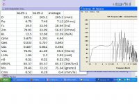
I did pull the specs off them using wt3:
http://www.diyaudio.com/forums/attachments/subwoofers/240235d1316166459-kef-b139-b139.jpg
One driver was very out from the other, as you can see in the above link-will try and re-measure them asap!
Apologies for your wasted efforts
[/FONT]
I'm guessing all this work has been wasted!
I did pull the specs off them using wt3:
http://www.diyaudio.com/forums/attachments/subwoofers/240235d1316166459-kef-b139-b139.jpg
One driver was very out from the other, as you can see in the above link-will try and re-measure them asap!
Apologies for your wasted efforts
[/FONT]
Oliver, thanks for your detailed post #23 above has helped clarify things for me
RE the isobaric-how much smaller could it make the enclosure? I know for "common" encloures it's half the space for the same extension or the same space for doubl the extension (give or take)-so could I keep the enclosure sixe, increase the horn length and tune lower?
OT: I've been told on this forum that isobaric doesn't lower distortion as we'd all been told for years-infact it could increase it! I'm trying to prove/disprove this, but have no suitable test equipment-trying to get DIYMA onto the subject with their Klippel.
Hi TheBaronGroog,
Maybe it'll give you or someone else a starting point. That would be worth it to me.
Regards,
Oliver, you legend! I'll have to remodel the output 1st-hope this works as well with the TS I've got!
Seems everyones efforts haven't been wasted
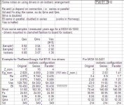
I've kept the enclosure the same and entered in the averaged TS from the two drivers I have-at this point it's the best way I can see of doing it-will add more SPL responses from the independant B139 TS spec too:
I've kept the enclosure the same and entered in the averaged TS from the two drivers I have-at this point it's the best way I can see of doing it-will add more SPL responses from the independant B139 TS spec too:
Attachments
Hi TheBaronGroog,
The single best investment for the loudspeaker design hobby may well be a woofer tester, e.g.: WT3 or so.
It's a while back, but I have build a number of isobaric enclosures, mainly because of woofers the T/S parameters of which seemed to have been invented by the sales department at MCM. Isobaric enclosures work, no doubt there. Manufacturers will usually not go there because of the added cost, and because they can have a driver build to suit their requirements.
I'll attach a spreadsheet I just updated. Don't take it for more than you paid for it. If you can: mount the drivers in clam shell format and measure the T/S parameters.
As to Post #29, only one way to find out.
Regards,
The single best investment for the loudspeaker design hobby may well be a woofer tester, e.g.: WT3 or so.
It's a while back, but I have build a number of isobaric enclosures, mainly because of woofers the T/S parameters of which seemed to have been invented by the sales department at MCM. Isobaric enclosures work, no doubt there. Manufacturers will usually not go there because of the added cost, and because they can have a driver build to suit their requirements.
I'll attach a spreadsheet I just updated. Don't take it for more than you paid for it
. If you can: mount the drivers in clam shell format and measure the T/S parameters.As to Post #29, only one way to find out.
Regards,
Attachments
Last edited:
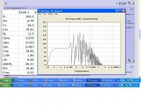
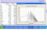
Right, remeasured the drivers, but didn't have the time to do added mass/known volume so have just got a fresh comparison between the drivers and also measured them mounted isobarically face to face. Looks like I didn't botch the measurement as both came out pretty much the same as before Will get them both hooked up for some burn in and see if it brings them more in line with each other-otherwise I'm just going to have to accept they'll be a little offf from each other or use some different subs: got a pair of REL 8", pair of IDQ10's and a Pioneer flat sub that would all give the right load for the amp I'll be using.
Will get them both hooked up for some burn in and see if it brings them more in line with each other-otherwise I'm just going to have to accept they'll be a little offf from each other or use some different subs: got a pair of REL 8", pair of IDQ10's and a Pioneer flat sub that would all give the right load for the amp I'll be using.Attachments
Last edited:
...got a pair of REL 8"...
The clearout ones that were on ebay about five years ago? If so, so have I. Strangely, currently in an isobarik BR of about 30 litres.
Not using them at the moment though, as the old Maplin mosfet amp I powered them with self destructed...
They may have come from there a friend had 8 of them in his ML, now he has 8 Focal 5" subs and I had the two REL and the IDQs off him-Yuri on talkaudio and Diyma, not sure if he frequents here. Not done enaything with them except pull the specs with WT3! Was planning an underbed enlosure for them-they may now make it to the living room...
I've decided to go ahead with this and just see what the output is like, got a friend with CNC facilities so will get him to do the cutting and then get the glue and screws out
Thanks for everyones assistance, will post some pics of the build process as and when it starts!
Thanks for everyones assistance, will post some pics of the build process as and when it starts!
B139 tapped horn
Hi
I have just unpacked two new B139s that I bought back in 1980 (no jokes please) to build the Linkwitz system. The satellites were built but not the bass unit because we went overseas. I have been reading about tapped horns on this forum and others and am keen to have a go. I have relevant skills having built the Pro9TL decades ago, bandpass units and various sealed boxes. I can configure and set up Brutefir on Linux and design active filters. I have never built a tapped horn and so far have read tutorials and downloaded Hornresp.
I am very keen to hear how this project has been developing since the last post. There are some clear limitations of the B139 but I am more interested in depth than power. My units are matched SP1044 units with an fs of 25 and power of 100 watts. I will need to measure them properly before finalising the design. I am not really interested in an isobaric design.
Any pointers?
Kind regards
Martin
Hi guys, hope you're all well
I've been on a little audio/forums sabbatical, while starting a new business and moving home, so I put the building of this little project on the back burner for a while.
The business is now open and doing well, the home is finally moved into and the pile of audio equipment needs assembling into a working system-with a bit more space to play with
I've been granted free reign over the size of the subwoofer - provided I can put the flat screen on it I'm good to go!
I've played around with Bjorno's design, increasing dimensions/volume, but haven't really succeeded in doing anything other than lowering the F3-but also the SPL. I'll be teaming this with a set of 3-way floor standers (6.5" MB, Ribbon and Tweeter), so don't need it to go as high or flat, but would like it to go lower and maintain or increase SPL-what say you? Possible?
Martin,
As you can see I've not built mine yet-though very keen to start! They are very similar to a 6th order BP in theory and in SPL response to a standard ported box-however as they're using both sides of the cone you have effectively double the x-max, so while on the same power the TH may only be as loud as the BR you are only using half the x-max, so you can turn it up some more.
Good thread:
http://www.diyaudio.com/forums/subwoofers/195480-why-tapped-horn-more-efficient-than-ported.html
Mine will be part on an active system, I scored a Sonance 12ch amp on ebay and will be running everything actively-however I am currently having to look at a bit of a Heath Robinson approach regarding the sub-woofer crossover. I have a decent 3-way active crossover which will handle the floor standers, and I was going to use a cheap car audio 2-way on the "low" out put of the three way to split it again-how hard is it to design and build a simple active crossover?
Just saw this thread and the ideas and thought of one thing since you haven't built it yet:
If you still plan to use dual drivers then you could invert one of them to reduce second order distortion at the lower frequencies, Danleys for example do it in several of their designs.
If you still plan to use dual drivers then you could invert one of them to reduce second order distortion at the lower frequencies, Danleys for example do it in several of their designs.
- Status
- This old topic is closed. If you want to reopen this topic, contact a moderator using the "Report Post" button.
- Home
- Loudspeakers
- Subwoofers
- Please help me fold my horn!!