Long story short I have 2 10 inch Pioneer Car subs Model TS-W255C That I have no use for.
So im looking to have a bit of a play with them and make something cool. Doesnt have to use both, but again would be nice.
Throw out some options, try to keep the box size reasonable.
What do people think would work well with this sub, i mapped out a vented box of 30L to 35hz but that seems a bit boring.
Thanks in advance for the help
maybe you could do a version of the ODougbo isobaric.
http://www.diyaudio.com/forums/subwoofers/203345-isobaric-less-then-20-a.html
col.
http://www.diyaudio.com/forums/subwoofers/203345-isobaric-less-then-20-a.html
col.
Another option if you are into electronics it to put them in very small sealed boxes and then run the signal through either a linkwitz transform or the ESP Electronically Assisted Subwoofer (EAS) circuit. I actually run 2 low profile Pioneer 10" subs in this way in a small apartment. The low bass they achieve is uncanny.
Sub-Woofer Controller
or if you can afford the PCB:
P48 Sub-Woofer Controller (Rev-A)
col.
Sub-Woofer Controller
or if you can afford the PCB:
P48 Sub-Woofer Controller (Rev-A)
col.
I tried to model the sub/subs in a bandpass design but it didnt look pretty.
These are the only specs i could find
They were from Pioneer TS-W255C 10" 4-ohm Component Subwoofer - Features & Specs at Crutchfield.com
I will say that a folding horn sub does intrigue me a lot.
Im no expert, in fact i am a box design virgin, this will be the first box i make of sorta my own design. The others I have made have been manufactures specs for car subs.
These are the only specs i could find
They were from Pioneer TS-W255C 10" 4-ohm Component Subwoofer - Features & Specs at Crutchfield.com
Size 10 -inch Impedance 4 ohms Cone Material Aramid fiber IMPP Surround Material Fiber-woven urethane Ideal Sealed Box Volume (cubic feet) 1 Ideal Ported Box Volume (cubic feet) 1.1 Port diameter (inches) 3 Port length (inches) 8 Free-Air No Dual Voice Coil No Sensitivity 87 dB at 1 watt
Frequency Response 18 - 2500 Hz RMS Power Range (Watts) 50-350 Peak Power Handling (Watts) 700 Top Mount Depth (inches) 5 5/16 Bottom Mount Depth (inches) 6 1/16 Cutout Diameter or Length (inches) 9 1/8 Vas (liters) 24.881 Fs (Hz) 35 Qts 0.351 Xmax (millimeters) 11.2
I will say that a folding horn sub does intrigue me a lot.
Im no expert, in fact i am a box design virgin, this will be the first box i make of sorta my own design. The others I have made have been manufactures specs for car subs.
Put them magnet-to-magnet in a small as possible box. Add some serious low-end boost.
Not sure what this means, are you referring to using a controller as refrenced above.
The apposed mounting effectively eliminates box movement in the "opposite" direction of the piston motion because the 2 drivers create and equal force in opposite directions when accelerated outward or inward simultaneously. Coupling the drivers together takes that the next step, removing front baffle flex from the picture.
By coupling do you mean make the box so that the magnets are hard up against eachother.
How will the magnets interact with eachother? will they effect eachothers voice coil enough to matter.
Wont it be hard to mount the woofers with the magnets pushing against eachother?
What you have said makes sense, and it does sound very intriguing.
How will the magnets interact with eachother? will they effect eachothers voice coil enough to matter.
Wont it be hard to mount the woofers with the magnets pushing against eachother?
What you have said makes sense, and it does sound very intriguing.
..Folded horns are tempting, just unsure where to start with a design...
Hi,
Agree, and would provide superior SQ if compared to a simple ported design.
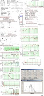
Here is a OD-TL suggestion for the Pioneer TS-W255C drivers using the advertised T/S parameters that would work well even if the Qm values of the drivers,after a burn in period, in the reality(I suspect), would show up with lower values. (Though if using measured parameters: I recommend to build a T-TQWT sub (maybe a Push-Push variant)
 )
)Note: This suggestion is equipped with a sufficient large terminus area to allow maximum excursion limit power levels(~710W) to be used, thus is not restricted by turbulent air velocities like a sane size BR port would show up with if the box volume stays between 1-2 cu.ft.
b
Attachments
Where is all that info from? Its a lot to take in, and 3/4 of it I dont understand.
Im compedent in building the boxes, the design is the part i want to learn but have a very limited knowladge.
OD-TL, does this mean Offset Driver Transmission Line? If so can someone explain the offset driver part?
Im struggling to even take out the dimensions from all the information you have given me. Overwhelming, but im sure it will become very useful once i understand it.
Where is all that info from? Its a lot to take in, and 3/4 of it I dont understand.
Hi, The cut and paste information is the result when entering your driver T/S into MJK:s and David McBean's programs.
..OD-TL, does this mean Offset Driver Transmission Line? If so can someone explain the offset driver part?..
If a driver is placed at the largest Tube area (in Mjk= the So area... =S1 in HR) the Offset Driver TL would turn into an ordinary TL or in HR a Nd TL.
The offset distance is in HR= L12 or = ξ*L in MJK- program.
..Im struggling to even take out the dimensions from all the information you have given me. Overwhelming, but Im sure it will become very useful once i understand it..
I think all necessary important information is included but I could be wrong.
b
Last edited:
I think all necessary important information is included but I could be wrong
Im sure it is, Im just struggling understanding it.
I think i need a dummies guide to Transmission Lines.
I wouldn't suggest mounting them in such a small box that the magnets are touching, rather, couple the units together with say, a brace held in place in the center of the box held in place by other cross bracing, such that when you load the drivers, the magnets are pressed against the brace that runs to the other magnet. It will require some fine wood working to get the size perfect, but in the end, it should work out such that when you tighten down the bolts to hold the driver in place, there should be a resulting tension on the center brace from the magnets being pressed against it.
T/S specs should be used to find an appropriate box size. If you want to go small sealed and EQ out the bottom end, I suggest finding the box size where Xmax and thermal limits are roughly evenly matched. Shoving drivers in boxes that cause you to reach thermal limits before Xmax limits is a poor use of available drivers. I would want to hit Xmax limits before thermal personally. (I came up with ~0.7-1.0 ft^3 sealed for a pair of drivers as the sort of minimum box size I would want to go)
T/S specs should be used to find an appropriate box size. If you want to go small sealed and EQ out the bottom end, I suggest finding the box size where Xmax and thermal limits are roughly evenly matched. Shoving drivers in boxes that cause you to reach thermal limits before Xmax limits is a poor use of available drivers. I would want to hit Xmax limits before thermal personally. (I came up with ~0.7-1.0 ft^3 sealed for a pair of drivers as the sort of minimum box size I would want to go)
Last edited:
That was something that i had thought of, and in reality wouldnt be too hard considering i have a thicknesser so as long as i was within 1-2mm (which isnt a problem) i will be able to fine tune the width of the brace.I wouldn't suggest mounting them in such a small box that the magnets are touching, rather, couple the units together with say, a brace held in place in the center of the box held in place by other cross bracing, such that when you load the drivers, the magnets are pressed against the brace that runs to the other magnet. It will require some fine wood working to get the size perfect, but in the end, it should work out such that when you tighten down the bolts to hold the driver in place, there should be a resulting tension on the center brace from the magnets being pressed against it.
I came up with ~0.7-1.0 ft^3 sealed for a pair of drivers as the sort of minimum box size I would want to go
Pioneer themselves reccomend 1.0ft^3 for a single, id assume that would just then double for 2.
- Status
- This old topic is closed. If you want to reopen this topic, contact a moderator using the "Report Post" button.
- Home
- Loudspeakers
- Subwoofers
- Help me with ideas for a dual 10 inch subwoofer box