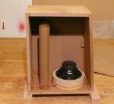
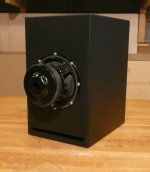
Some may be familiar with the design, although I used cardboard tubes instead of a slot port.
Also ran this in WinISD and Perfect Box; the results were similar so went with a 1cf box and dual ports 16” long [the next box I may go back to a slot port]
The woofers are 6 ½” Factory Buyout, I bought 4 for $8 each.
http://www.parts-express.com/pe/showdetl.cfm?Partnumber=299-114
They modeled okay; it does have a bit of a shark tail contour, 3db increase at 25hz. I’ve been adding a little extra at the bottom for such a long time I don’t think I would like anything else.
This Isobaric box appears to have some power, a few more easy steps and I’ll do a final glue up. I like to clamp and check the tuning before final assembly. I was pleasantly surprised, the tuning and the response was as expected (and some 25hz bass).
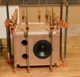
Not a bad little woofer, the surround is light rubber; I wish it had more than 4 holes [they say never drill a basket].
The laminate rings are pretty easy, it only took three rings; i.e. the woofers are 2-¾” apart.
*I also added a 10" PR ($18) to the last order, I wouldn't mind trying that with the next build.
Also ran this in WinISD and Perfect Box; the results were similar so went with a 1cf box and dual ports 16” long [the next box I may go back to a slot port]
The woofers are 6 ½” Factory Buyout, I bought 4 for $8 each.
http://www.parts-express.com/pe/showdetl.cfm?Partnumber=299-114
They modeled okay; it does have a bit of a shark tail contour, 3db increase at 25hz. I’ve been adding a little extra at the bottom for such a long time I don’t think I would like anything else.
This Isobaric box appears to have some power, a few more easy steps and I’ll do a final glue up. I like to clamp and check the tuning before final assembly. I was pleasantly surprised, the tuning and the response was as expected (and some 25hz bass).
Not a bad little woofer, the surround is light rubber; I wish it had more than 4 holes [they say never drill a basket].
The laminate rings are pretty easy, it only took three rings; i.e. the woofers are 2-¾” apart.
*I also added a 10" PR ($18) to the last order, I wouldn't mind trying that with the next build.
Attachments
My first post ever on diy. Your isobaric inspires me to get to a project I've had on the shelf for a few years. I have 8 vifa 8" woffers from a speaker that ended up not working. I want to build a double isobaric with 4 per side and mate that up with a 4" vifa mid and a vifa tweeter.Crossover will be simple to start as that is a very weak area for me.This will take time but I"ve been sitting on these drivers for a few years so what's a while longer? Thanks for the kick in the pants.
If I was to describe the sound, it’s a slam, bubble and/or chug. I have a MCM 8” Iso in the shop, it reaches out and grabs you.
The two in the HT I moved up on 12” metal stands; should have done that long ago, it was a big improvement (by adding detail in the bass).
I find them remarkable.
8 working Vifa woofers? What’s the model #?
The two in the HT I moved up on 12” metal stands; should have done that long ago, it was a big improvement (by adding detail in the bass).
I find them remarkable.
8 working Vifa woofers? What’s the model #?
I don't use plate amps (do have one on the bench) I've been using, Rotel, 120 watt stereo amps, e.g. RB 980BX. I had an Adcom 60watt stereo amp powering one for a long time, it had a very nice sound.
I'll try this 6-1/2” Iso in shop, HT and maybe even the truck cab; that 25hz would sound great in a cab.
I'll try this 6-1/2” Iso in shop, HT and maybe even the truck cab; that 25hz would sound great in a cab.
I did not measure with a mic, but reasonably sure the predicted curve is pretty close to the actual response.
E.g. @ 25hz the bass is very strong, I did have to move back from the speaker about 15'. Also my impression was the speakers were pretty good; everything was rattling: ducts, table, test equipment, basically different parts of the room at different frequencies.
What do you think about the 10" PR, is this Iso box and speaker(s) a candidate?
Thanks for the link to the diy subwoofer page, I’ll be reading up on that.
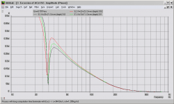
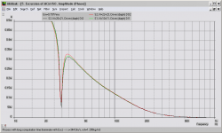
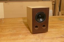
I've said before that mounting drivers using a tunnel is a sub-optimal method. The "tunnel" graph illustrates why. It's from the model I did of your MCM 55-2421 design. Note that the "outer" (visible) driver (red line) will hit its excursion limits well before the inner driver (black line). The green line shows the theoretical response for drivers with no space between them. Mounting the drivers face-to-face improves the performance considerably ("clamshell" graph).
Attachments
Thanks for the graph Don. I did make many, many boxes and just went with the ones I liked and thought worked best. The clamshell box was okay, it had a bit more output, however something about the tunnel gives the box/woofer(s) a solid sound.
I do have two more of these 6 1/2 “ woofers and was going to build another box, maybe with a 10" PR if it looks good in WinISD. The fact that there is a PR makes life a whole lot easier as far as removing the back (active) woofer; I’ll go with a clamshell.
I do have two more of these 6 1/2 “ woofers and was going to build another box, maybe with a 10" PR if it looks good in WinISD. The fact that there is a PR makes life a whole lot easier as far as removing the back (active) woofer; I’ll go with a clamshell.
Attachments
Last edited:
... I did make many, many boxes and just went with the ones I liked and thought worked best. ...]
That's a valid philosophy. Where bass is concerned, the response of the speaker alone becomes less important than the overall response in its intended location. "Commercial" speakers have to sound acceptable in a range of rooms. With DIY we have the opportunity to consider the speaker and room as a system, and it is no harder to build a speaker specifically designed for a room (and personal listening tastes) than it is to build a "compromise" speaker.
I've said before that mounting drivers using a tunnel is a sub-optimal method. The "tunnel" graph illustrates why. It's from the model I did of your MCM 55-2421 design. Note that the "outer" (visible) driver (red line) will hit its excursion limits well before the inner driver (black line). The green line shows the theoretical response for drivers with no space between them. Mounting the drivers face-to-face improves the performance considerably ("clamshell" graph).
Don, the graphs are convincing enough, although a couple of questions:
Would a parallel (4ohm) connection help keep the two drivers in sync (vs. series)?
Would a good heavy/powerful stereo amp keep them “together” in parallel mode?
What about a 6 ½” driver? I would have to think a smaller cone would have fewer problems than 10’s and up.
The tunnel is minimal size and air tight (the tunnel could be made hour glass shape).
The new box will be done soon, added a 1/4” masoite to the front so I could flare the port holes.
Win some and lose some
Well here it is.....
It's okay, too much low end. All the bad characteristics of a tunnel are showing with this experiment.
OR maybe I expected too much from the “toy” drivers.
The cones are moving hard and not a lot of output, well there is very low bass and not much else, I moved the crossover up to 100hz, that helped some.
The MCM box is about 4x as “powerful”; and this not a total disaster, not going to break it apart, not yet anyway. It will be fine for a computer station, maybe the car.
Attachments
Would a parallel (4ohm) connection help keep the two drivers in sync (vs. series)?
The model I used was parallel connected already. I just now tried a series connection, it looks even worse. You need to avoid series connection unless you can ensure that both drivers are subject to the same load.
Would a good heavy/powerful stereo amp keep them “together” in parallel mode?
The model assumes a perfect amplifier. Any real world setup would perform worse.
What about a 6 ½” driver? I would have to think a smaller cone would have fewer problems than 10’s and up.
It's nothing to do with absolute cone size - it's the relationship between the drivers' characteristics and the volume of the inter-driver space.
The tunnel is minimal size and air tight (the tunnel could be made hour glass shape).
Unless you are specifically after the look of a conventional speaker (visible cone facing out), I would recommend face-to-face mounting. To avoid the "outer" driver protruding, you could build the enclosure as you do now, but mount both drivers on the inner end of the tunnel. Or just recess the end of the baffle where the drivers are mounted. You could make a very tidy square section grille to fit into the recess and provide a flush front look.
Note that the "different excursion" problem mainly applies to vented enclosures. It does occur with sealed enclosures but to a lesser degree. The excursion differential is more or less proportional to the ratio of the volumes of the main enclosure and the inter-driver volume. With a vented enclosure, the rear enclosure can be thought of as very "small" at resonance - the enclosure pressure is almost equal to the pressure exerted by the driver, which is why the driver excursion falls to a minimum at resonance. That's why even a small inter-driver volume becomes significant at resonance of a vented enclosure.
Hmmmm......
I see a certain very poor isobaric design has hijacked this thread,
very poor show. I sick of reading about how great one man's
poorly designed subwoofer is in his opinion, its boring.
rgds, sreten.
On the contrary, if you look at the opening post, this thread is all about that certain isobaric design. You are welcome to express your opinion of it, which you have. If you find it boring, DIYAudio is a large board. I'm sure there are many other threads you will find interesting.
")
- Status
- This old topic is closed. If you want to reopen this topic, contact a moderator using the "Report Post" button.
- Home
- Loudspeakers
- Subwoofers
- Isobaric - less then $20