i have some midfi unmarked 10 inch subwoofer. play pretty well in ported design but at moderate levels. i am making an experiment for lineartity and greater power handling by improving BL curve linearity and dual spider.
Basically the idea is from compound puu push /isobarick subwoofer loading. The idea is to take it further from here. As we know that in ideal isobarik loading there is non linearity in trapped air, Vas is halfed so is 3db loss inefficiency. Lower distortion one motor is pushing while other pulling, the BL curve gets symettrical.
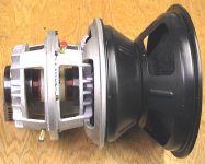
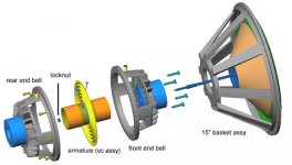
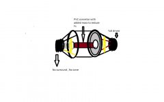
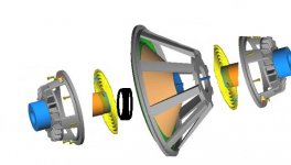
I intend to remove the surround and cone of one woofer , now i would have one motor with voice coil and basket. Invert it on top of the second woofer , bolt the two bakets together and connect the voicee coils with PVC pipe of the size of the voice coil i.e 3 inch with lenght of exact space between then glue them terogether.
Now both motors and two coils oare physically connceted in pull-push mehtod, BL curve non linearity is corrected and so is spider. A variation is like this
:
But obviously it would have one cone , one surround, two motors , two coils. Now my question:
Since one surround and cone is removed its compliance would be altered, would it introduce any distorition ? Fs would vary ?
Xmax would not increase i know but i am aiming at SQ here. suggestions please pictures to follow quickly.
Basically the idea is from compound puu push /isobarick subwoofer loading. The idea is to take it further from here. As we know that in ideal isobarik loading there is non linearity in trapped air, Vas is halfed so is 3db loss inefficiency. Lower distortion one motor is pushing while other pulling, the BL curve gets symettrical.
I intend to remove the surround and cone of one woofer , now i would have one motor with voice coil and basket. Invert it on top of the second woofer , bolt the two bakets together and connect the voicee coils with PVC pipe of the size of the voice coil i.e 3 inch with lenght of exact space between then glue them terogether.
Now both motors and two coils oare physically connceted in pull-push mehtod, BL curve non linearity is corrected and so is spider. A variation is like this
:
But obviously it would have one cone , one surround, two motors , two coils. Now my question:
Since one surround and cone is removed its compliance would be altered, would it introduce any distorition ? Fs would vary ?
Xmax would not increase i know but i am aiming at SQ here. suggestions please pictures to follow quickly.
Attachments
Have you reviewed JBL's Differential drive? Worth looking over given your experimentation.
On your prototype, I'd cut some windows out of the enclosed spider sub-assembly for further ventilation, since you're going to all this trouble. Also, I'd want to use shorting rings and extended poles to give a head-start on the low distortion part.
Will be interesting to see where this takes you!
On your prototype, I'd cut some windows out of the enclosed spider sub-assembly for further ventilation, since you're going to all this trouble. Also, I'd want to use shorting rings and extended poles to give a head-start on the low distortion part.
Will be interesting to see where this takes you!
nice experiment,i like it.
i think the hole moving asambly should be in ballance ,i think a pvc pipe would become to heavy compared to the cone,but who knows.
the added weight of the extra voice coil and suspension wil lower fs already.
maybe try something lighter to connect the coils,paper maybe.
i think the hole moving asambly should be in ballance ,i think a pvc pipe would become to heavy compared to the cone,but who knows.
the added weight of the extra voice coil and suspension wil lower fs already.
maybe try something lighter to connect the coils,paper maybe.
The differetial is different. it uses 3 stacked magnets and two coils on a single former to maintian linearity of BL curve , symmetr but no uniformity, secondly the spider and nno linearlity in both directions as well as control over lateral movements in my design..
I think its a good idea for DIY and not commercially viable for looks and odd intallation, and i think going to loose some SD as cone centre would be locked outiwth PVC pipe. Again it would be running i series to ensure same current through both coils.
Any guess on Fs, Vas and Qts, Qms, Qes. ??? and SQQQQ
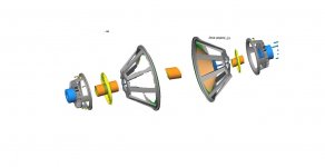
Co-Drive is the first figure. its different. see the last post picture. However is one way of doing too difficult. This can be done by removing , one surround, inverting the subwoofer and just paste it un-amended woofer, or remove the cone as well and connect the first woofer VC with a light pipe to the second woofer.
You can simulate this in AkAbak. I think you will find that it will perform slightly better than a standard "isobaric" configuration, but probably not enough better to make it worth the effort.
I used AkAbak to compare a "standard" isobaric (2 drivers mounted face to face, thus a small air compliance between them) with a "rigid" isobaric (no compliance between them). The overall performance was almost unchanged, but there was a difference in excursion between the two drivers in the "standard" isobaric configuration.
I used AkAbak to compare a "standard" isobaric (2 drivers mounted face to face, thus a small air compliance between them) with a "rigid" isobaric (no compliance between them). The overall performance was almost unchanged, but there was a difference in excursion between the two drivers in the "standard" isobaric configuration.
what you mean by "difference in excursionbetween the two drivers in the standard isobaric configuration " ??? Thats what we want to explore here
I think even the most rigit isobarik cannot substitute a mechanical coupling especially when you are pulling the cone out, i mean the foam surrounds are porous, the air is non-linear, at best its thress resonating springs with 2 weights in isobarik as compared to one weight between two springs. easy to predict and work around mor elinearity less surprises.
The objective is learning... and possible some very good SQ out of ordinary drivers. i hope i will have support here.
Any ideas what to measure, THD ? SPL, Qtc, Fs etc???/
Basically as i see most SQ drivers have low Fs usually and low senisitivy, a trade off for more low ouput than higher bands, but having greater MMS and needing greater BL, more magnets for keeping the coil in linear region, and over heating ..........list goes on so for even modest improvement in SQ and motor control over a heavy cone we need a way tooo huge motor and cost.........hence the approach. two motors doing the work of one cone with each coil in different relative position to field force they almost would be linear.... better than stacking 3 magnets why not two magnets doing pull-push in tandem. At least theoretically.
regards
For any practical isobaric configuration, even face to face for minimum volume, the excursion of the two drivers differs significantly. Rigidly coupling the two drivers reduces the excursion difference to zero, but doesn't significantly affect the overall response. My original reason for simulating it was to look at what would happen if the enclosure between the drivers was the same volume as the "rear" enclosure. I was surprised to see how even a small volume between the drivers made a significant difference.
As for your thoughts on having the coupled coils in different positions to improve linearity, this will only work if the BL product of each coil is non-linear through its travel, so that the combined force is linear. I believe there is a patented system that does this with a single motor/coil assembly, "Alpine X2" or some similar name.
As for your thoughts on having the coupled coils in different positions to improve linearity, this will only work if the BL product of each coil is non-linear through its travel, so that the combined force is linear. I believe there is a patented system that does this with a single motor/coil assembly, "Alpine X2" or some similar name.
- Status
- This old topic is closed. If you want to reopen this topic, contact a moderator using the "Report Post" button.
- Home
- Loudspeakers
- Subwoofers
- compund motor subwoofer