Hi permo,
Art (weltersys) just opened a new thread:http://www.diyaudio.com/forums/subwoofers/207771-new-lower-cost-b-c-18-a.html , that driver will actually work well in a T-TQWT. Might be a good one for you to try in Hornresp. My guess is that you'll end up with about a V_ext=10ft^3 enclosure.
Regards,
Agree:
b
")
Attachments
600 watts = 120 db at 20 hz in half space. pretty cool.
I am quite sure i haven't even come close to maximum output on my dual TB speaker, I can't imagine what that big pig would do. I have to say that I am amazingly happy with what I have. A simple 150 watt amp with this design is literally capable of house shaking output. Its simply a joy to listen to such effortless and powerfull bass. It brings the whole system to life.
I had a boston acoustics powered sub with a 10 inch driver. It cost me right around four hundred dollars. I am maybe $300 down for this subwoofer...counting the external amplifier. I hate to think what this type of performance would cost if you were to try and buy it in a premade package.
Last edited:
Hi permo,
By the way, for a coffee table sub, take a look at this thread, Post #38: http://www.diyaudio.com/forums/subwoofers/203827-20-30hz-tapped-horn-studio-ande-drivers-4.html
Those JBL's are really nice drivers, and priced reasonably.
Regards,
By the way, for a coffee table sub, take a look at this thread, Post #38: http://www.diyaudio.com/forums/subwoofers/203827-20-30hz-tapped-horn-studio-ande-drivers-4.html
Those JBL's are really nice drivers, and priced reasonably.
Regards,
Hi permo,
By the way, for a coffee table sub, take a look at this thread, Post #38: http://www.diyaudio.com/forums/subwoofers/203827-20-30hz-tapped-horn-studio-ande-drivers-4.html
Those JBL's are really nice drivers, and priced reasonably.
Regards,
That looks great. I will have to check into stealing a pair of those somehow.
Hi permo,
Here is one set on ebay: 2 JBL GTO1214D CAR AUDIO STEREO 12" 4-OHM GTO POWER SUBWOOFERS/SUB WOOFERS PAIR | eBay
Regards,
Here is one set on ebay: 2 JBL GTO1214D CAR AUDIO STEREO 12" 4-OHM GTO POWER SUBWOOFERS/SUB WOOFERS PAIR | eBay
Regards,
Hi permo,
Here is one set on ebay: 2 JBL GTO1214D CAR AUDIO STEREO 12" 4-OHM GTO POWER SUBWOOFERS/SUB WOOFERS PAIR | eBay
Regards,
Got dang....that is super tempting!
Oliver and Bjorno Rock!
I just love this thread! And I just can't stand it anymore, so I have to ask a few questions.
I have a couple of W8Q-1071F's lying around and I think I just "have" to build this thing. I know how to use all the measurement tools, would be happy to post pictures, tests, etc. I am still learning the modeling tools.
I would be interested in hearing your comments on building two of these with one driver a piece instead of one with two drivers.
I would like to simplify the cuts to standard board sizes so that it would be easier to cut without a table saw, etc. In other words, use 48" X 10" boards, half cut panels, etc. Or another way to say it is turn it into a kit my kids and friends could build. I know this will change things, but looking at the design, it looks like it could be adjusted inward (10" instead of 10 5/8" ) just a little to make it easier to build.
I was also thinking, why not just make the one side removable? You could use a ton of screws, or a few key placed bolts from side to side. And of course the hot glue trick.
Basically. Now that we know the thing works, are there some simple things that we could tweak it so that all of my friends could make them!
There are a bunch of us that get together, tweak, tune and play with this stuff on a regular basis, and I would love to hear any insights or additional thoughts that you might have for the group.
Thanks again everyone!
A well executed DIY job is always rewarding...
In time grasshopper,in time...
Why not involve SWMBO to camouflage your creation: Picture example:
Time to renew the House insurance?
Your sub is a point-source pressure device, the T-TQWT internal air volume velocity is converted into pressure at the port,wasting very little power to sweep the floor in front of the terminus if you have an adequate HPF.
Oliver is the one who should recieve credits for this design: My contribution is if compared with his IMO very modest..
b
PS: The potted-plant placed on top of the enclosure is an Hoya...needs little water and a share of double-bass music in order to flourish.
Hi uptime,
Basically, your looking at reducing all the cross-sectional areas by 2, and maintaining the duct lengths. If the area around the back of the driver gets to be too tight, you may have to add a coupling chamber from the back of the driver to the duct. That can be accounted for easily in Hornresp (throat chamber).
I like the idea to make one side removable, screws every 6-8 inches, and weatherstripping should do the trick.
But, you are still looking at a complete redesign, especially if you have to introduce a throat chamber.
Regards,
Attachments
Hi Y'all,
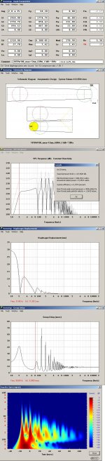
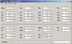
I changed the design for a single driver T-TQWT using the TangBand W8Q-1071D around a few times, and this is my final version. I was able to get the driver into the enclosure without a coupling chamber. The dimensions should be easier on standard sheets of wood (4' x 8').
Regards,
I changed the design for a single driver T-TQWT using the TangBand W8Q-1071D around a few times, and this is my final version. I was able to get the driver into the enclosure without a coupling chamber. The dimensions should be easier on standard sheets of wood (4' x 8').
Regards,
Attachments
Last edited:
You still rock!
Wow. I am impressed! I was trying to get my head around the layout and I started working on figuring out the cut sheets, etc. when I came back to the site and boom just like magic, it was there.
I am going to build a sample version of this thing (or at least slap it together). It will either be wonderful (my expectation), or we'll have a bit more firewood for the winter.
I will let you know either way.
Hi Y'all,
I changed the design for a single driver T-TQWT using the TangBand W8Q-1071D around a few times, and this is my final version. I was able to get the driver into the enclosure without a coupling chamber. The dimensions should be easier on standard sheets of wood (4' x 8').
Regards,
Perfect!
Very good design!
I've looked up my simulations for a single driver T-TQWT and found when entering/comparing your ACAD dimensions into HR almost no difference at all.
A trim point for this T-TQWT would IMO be to add a 2.2mH/0.85Ohm (18AWG) inductor in series with the driver.
A lot of drivers are not suitable for a T-TQWT due to the needed rear driver clearance but if implemented as a T-MLQWP (Tapped-Mass-Loaded Quarter-Wave -Pipe) it's IME easy to adapt to a compact simple enclosure.
b
Attachments

Hi bjorno,
Thanks for looking at this. The value of a series inductor should probably be re-evaluated after stuffing, and equalizing?
I also like your T-MLQWP, another way of simulating, and looking at pretty much the same enclosure type.
PE has a nice listing of inductors w/ impedance/resistance tables:Parts-Express.com - Air Core Inductors Index: 14 Gauge, 15 Gauge, 18 Gauge, 20 Gauge (I still like to wind my own.).
Regards,
Thanks for looking at this. The value of a series inductor should probably be re-evaluated after stuffing, and equalizing?
Hi Oliver,
Exactly, You don't want to add to much series resistance or a L value that is too close too or exceeds fm= 2x fs/Qes. (2x Pi x fm x L should be < (Re+re+Rg)); re = Inductor loss.
The focus should IMO be an improvement at in-band center SPL ,not the reduction of the small occurring peak near cut-off of the FR that always is smoothed by the stuffing(+foldings).
I also like your T-MLQWP, another way of simulating, and looking at pretty much the same enclosure type.
I noticed that too: I think this is the approach to improve BR designs that in case would suffer leak through off-band ripple from a too large/long port as if you stuff the port for to get rid of ripple,the whole definition of tuning low is counteracted form a much lower port level.
IMO,OTOH: The T-MLQWP should always be stuffed until the resonance level can be accepted after sub-amp LP filter is established, of course.
PE has a nice listing of inductors w/ impedance/resistance tables
Yes, I wind my coils too but for the present case:I picked the inductor data: 2.2mH/0.85 Ohm 18 Gauge from PE.
b
Work in progress!
Oliver,
This morning we bought two sheets of 3/4" MDF and this afternoon my youngest son and I started cutting and gluing pieces. My son, after we got about half way through the cuts, said to me, "Hey Dad, can I build the second one with you while you are putting together the first one?" "Sure! We've got the second piece of MDF, so why not?" So in the few hours we spent on it this afternoon, we have almost two subs finished!
After the glue dries on the smaller parts, on Monday, I was planning on taking a bunch of pictures of the layout and posting them. So yes, I will make sure that everyone gets a chance to see both of our handywork(s).
I did have a question about the total "pipe" length. It occurs to me that the little block below the port could be removed and increase the length back to close to where the original design calls for it. Also, then the port could move down. I am sure that there is a reason for this, but looking at it today, it would have made the design a little easier to cut and glue.
We are gluing all of the parts and countersinking everything with Spax and other cabinet screws. I just love those screws. Tight threads, easy driving, and you don't even need to pre drill in a lot of cases. Very clean finish. And best of all, no stripping of heads. Especially nice for kids. It will make more sense of how we put it all together when you see the pictures on Monday.
We learned a lot today.... The only really tricky parts to cut, glue and screw together were the pieces that flow around the back of the speaker. Most of the rest has been pretty easy to follow and the drawings have had most of the values and measurements when we needed them. I had to help my son cut all of the funny angles even though they aren't too complicated.
Because of the lengths and sizes of the pieces, you pretty much have to have a table saw. My neighbor was kind enough to let me borrow his table saw and the cuts were pretty easy then. There was one measurement that we had to calculate from the other measurements and at the same time get the right angles. But it only took a couple of minutes to figure out. Just a reminder to everyone, and those who are geometry challenged, the 90 degree means that you have 45 degrees on opposite sides, which means that since the board is 3/4" thick, the length of the board on the long side is 3/4" longer. Basic math, but many may not remember this from high school.
Personally (and of course to redeem myself with Oliver), we chose to glue all of the sandwiched pieces together, and then put the nice cabinet screws about every 6-8 inches. We also sanded all of the edges and angles because it is generally hard for neophytes like me to get them all to layout just perfect. Also, don't forget that the blade actually has some width, and so you can't just cut a 42 inch piece of wood down to the 14" and 28" piece. We also cut most of the pieces just a small bit larger to account for the saw blade, and then used the electric sander to clean it down to the correct size. This made the cutting of all of the boards much easier because so many of them are about the same size. And like I said earlier, it took us about the same about of time to cut and glue two full subs as it would have to make just one.
Since the TB driver doesn't come with a template, we found that the easiest way to get one is to trace and cut a sheet of paper based on the plastic lid that covers the driver when you first open the box. It is a nice way to get the right sized hole.
Next steps will be to lay all of the pieces out, take some pictures, glue the rest together, stuff it, screw the panels on and then run tests.
We are hoping to get all of this done on Monday. This would mean that we will have built two subs in about 8 hours worth of work. We'll see...
Thanks again for all of your help.
Talk to you on Monday.
Hi uptime,
It would be great to see some pictures of your effort, if permo doesn't mind this being in his thread. When you "...slap it together..." be sure to avoid leaks.
Regards,
Hi uptime,
It would be great to see some pictures of your effort, if permo doesn't mind this being in his thread. When you "...slap it together..." be sure to avoid leaks.
Regards,
Oliver,
This morning we bought two sheets of 3/4" MDF and this afternoon my youngest son and I started cutting and gluing pieces. My son, after we got about half way through the cuts, said to me, "Hey Dad, can I build the second one with you while you are putting together the first one?" "Sure! We've got the second piece of MDF, so why not?" So in the few hours we spent on it this afternoon, we have almost two subs finished!
After the glue dries on the smaller parts, on Monday, I was planning on taking a bunch of pictures of the layout and posting them. So yes, I will make sure that everyone gets a chance to see both of our handywork(s).
I did have a question about the total "pipe" length. It occurs to me that the little block below the port could be removed and increase the length back to close to where the original design calls for it. Also, then the port could move down. I am sure that there is a reason for this, but looking at it today, it would have made the design a little easier to cut and glue.
We are gluing all of the parts and countersinking everything with Spax and other cabinet screws. I just love those screws. Tight threads, easy driving, and you don't even need to pre drill in a lot of cases. Very clean finish. And best of all, no stripping of heads. Especially nice for kids. It will make more sense of how we put it all together when you see the pictures on Monday.
We learned a lot today.... The only really tricky parts to cut, glue and screw together were the pieces that flow around the back of the speaker. Most of the rest has been pretty easy to follow and the drawings have had most of the values and measurements when we needed them. I had to help my son cut all of the funny angles even though they aren't too complicated.
Because of the lengths and sizes of the pieces, you pretty much have to have a table saw. My neighbor was kind enough to let me borrow his table saw and the cuts were pretty easy then. There was one measurement that we had to calculate from the other measurements and at the same time get the right angles. But it only took a couple of minutes to figure out. Just a reminder to everyone, and those who are geometry challenged, the 90 degree means that you have 45 degrees on opposite sides, which means that since the board is 3/4" thick, the length of the board on the long side is 3/4" longer. Basic math, but many may not remember this from high school.
Personally (and of course to redeem myself with Oliver), we chose to glue all of the sandwiched pieces together, and then put the nice cabinet screws about every 6-8 inches. We also sanded all of the edges and angles because it is generally hard for neophytes like me to get them all to layout just perfect. Also, don't forget that the blade actually has some width, and so you can't just cut a 42 inch piece of wood down to the 14" and 28" piece. We also cut most of the pieces just a small bit larger to account for the saw blade, and then used the electric sander to clean it down to the correct size. This made the cutting of all of the boards much easier because so many of them are about the same size. And like I said earlier, it took us about the same about of time to cut and glue two full subs as it would have to make just one.
Since the TB driver doesn't come with a template, we found that the easiest way to get one is to trace and cut a sheet of paper based on the plastic lid that covers the driver when you first open the box. It is a nice way to get the right sized hole.
Next steps will be to lay all of the pieces out, take some pictures, glue the rest together, stuff it, screw the panels on and then run tests.
We are hoping to get all of this done on Monday. This would mean that we will have built two subs in about 8 hours worth of work. We'll see...
Thanks again for all of your help.
Talk to you on Monday.
Hi uptime,
Great to hear that you and your son are having a good time putting this enclosure together.
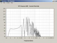
As to the "...total "pipe" length...": this is the result of optimizing the response in Hornresp. If you add the 5cm to L34 the result will be a glitch in the SPL response @ about 70Hz. I know that may, or may not be a problem after the box is stuffed as outlined in the drawing, but I like to start with something that looks clean.
For me, the design process is an iterrative one, design in Hornresp, take it to a drawing, adjust Hornresp to reflect reality (the drawing), and so on... Next would be building a prototype, and testing the acoustic performance... Oh yes, you are doing that part.
To making the wood cutting easier: a round port, combined with a single front panel seems easier to me than a slot port with a two piece front panel, and the round port would move the "little block below the port" down; both should work fine though (bye the way, the front panel and the back panel should be the same raw size, there was an error in part of the original drawing). The 14/28/42" pieces are not at all critical, as long as they are sealed to the side pieces, and allow sufficient air around the back of the woofer. Luckily you can get to the internal boards by removing the back-or front-, that makes caulking the board edges easy.
I'll attach a revision of the original drawing in Post #170:
Regards,
Great to hear that you and your son are having a good time putting this enclosure together.
As to the "...total "pipe" length...": this is the result of optimizing the response in Hornresp. If you add the 5cm to L34 the result will be a glitch in the SPL response @ about 70Hz. I know that may, or may not be a problem after the box is stuffed as outlined in the drawing, but I like to start with something that looks clean.
For me, the design process is an iterrative one, design in Hornresp, take it to a drawing, adjust Hornresp to reflect reality (the drawing), and so on... Next would be building a prototype, and testing the acoustic performance... Oh yes, you are doing that part
.To making the wood cutting easier: a round port, combined with a single front panel seems easier to me than a slot port with a two piece front panel, and the round port would move the "little block below the port" down; both should work fine though (bye the way, the front panel and the back panel should be the same raw size, there was an error in part of the original drawing). The 14/28/42" pieces are not at all critical, as long as they are sealed to the side pieces, and allow sufficient air around the back of the woofer. Luckily you can get to the internal boards by removing the back-or front-, that makes caulking the board edges easy.
I'll attach a revision of the original drawing in Post #170:
Regards,
Attachments
Hi permo,
Did you notice, that the little brother of your driver is on sale: Tang Band W69-1042J 6"x9" Subwoofer 264-837 , it would work well in a similar, smaller enclosure.
Regards,
Did you notice, that the little brother of your driver is on sale: Tang Band W69-1042J 6"x9" Subwoofer 264-837 , it would work well in a similar, smaller enclosure.
Regards,
Hi uptime,
Great to hear that you and your son are having a good time putting this enclosure together.
As to the "...total "pipe" length...": this is the result of optimizing the response in Hornresp. If you add the 5cm to L34 the result will be a glitch in the SPL response @ about 70Hz. I know that may, or may not be a problem after the box is stuffed as outlined in the drawing, but I like to start with something that looks clean.
For me, the design process is an iterrative one, design in Hornresp, take it to a drawing, adjust Hornresp to reflect reality (the drawing), and so on... Next would be building a prototype, and testing the acoustic performance... Oh yes, you are doing that part
To making the wood cutting easier: a round port, combined with a single front panel seems easier to me than a slot port with a two piece front panel, and the round port would move the "little block below the port" down; both should work fine though (bye the way, the front panel and the back panel should be the same raw size, there was an error in part of the original drawing). The 14/28/42" pieces are not at all critical, as long as they are sealed to the side pieces, and allow sufficient air around the back of the woofer. Luckily you can get to the internal boards by removing the back-or front-, that makes caulking the board edges easy.
I'll attach a revision of the original drawing in Post #170:
Regards,
Thanks Oliver. That explains it nicely. And thank you for taking the time to add the additional measurements. This will be a great help for other builders. I also saw the small error yesterday because the sizes didn't line up quite right, but as I remember it, it was less than an 1/8th of an inch, so I wasn't all that worried about it. My son is a bit of a math wiz, as a little kid he could see the answers for multiplying three digit numbers together and he picked up on it, but as I said it was close enough.
I think we are going to do the slot. I don't have the perfect equipment to cut great circles. It will also allow us to adjust things a little easier if we are way off, which I don't think we will be.
I was also thinking that I might run the speaker wire from the driver down through the little block towards the front of the speaker and then out the side (drawing front view). That way we will be able to seal things better and basically have a few baffles to keep the air from getting out places they shouldn't.
I love that the driver is on sale by the way. I got these ones around the holidays for $49 a piece. I wish they still sold them. Do you think this is because TB is closing them out and have something else coming or because parts express has some other motivation? Or because of something like the fact that they are a strange size, harder to work with, technically more challenging etc.?
Also, I noticed a "litle" spelling error on the drawing.
Thanks again for hanging in there with us on this project. I can't hardly wait to see how well these perform.
- Status
- This old topic is closed. If you want to reopen this topic, contact a moderator using the "Report Post" button.
- Home
- Loudspeakers
- Subwoofers
- Tang Band Tang Band W8Q-1071F 8 X 12 box reccomendation