After simming your driver in hornresp awhile, I'm convinced that this horn loading stuff is a lot more hype than anything. The best arrangement I could come up with produced similar efficiency and loading characteristics as the 6th order bandpass box I suggested above, however, the box would be nearly twice the size, and perform ~3db worse in maximum output compared to the 6th order bandpass configuration.
Well, the hornresp design in this example is 133 liters or so, which isn't that large and goes down to 20hz solid. I am not sure exactly how feasible this design is.
The problem with the 6th order is the 35hz to 90 hz effective passband. the gain is nice and fully appreciated, but I am looking to add some realism to movies, and 35hz isn't going to cut it.
So far the most realistic, and feasable configuration to take full adantage of my speaker design abilities is a 4.5-to 6 cubic foot ported enclusure tuned to 25-30 hz.
If i could figure out how to build the horn I would likely give that a try but as of right now, I don't have confidence in my ability to put those numbers into cutting wood.
Hi permo,
Post #21: "...confidence in my ability to put those numbers into cutting wood."
That is the problem, some enclosures model just fine, but the model cannot be converted into a physical reality (at least not easily). This is one of those, there is just not enough cross-sectional area to fit the drivers, and to properly fit the S34 duct length.
If you want to build something like this you may have to take a different approach. Instead of the S12 duct section you could substitue a coupling chamber (or call it: horn throat chamber), which could be sized to provide room for the drivers. You would still have to deal with the problem of where to place the S34 duct length.
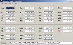
I'll attach a Hornresp input as an example:
Regards,
Post #21: "...confidence in my ability to put those numbers into cutting wood."
That is the problem, some enclosures model just fine, but the model cannot be converted into a physical reality (at least not easily). This is one of those, there is just not enough cross-sectional area to fit the drivers, and to properly fit the S34 duct length.
If you want to build something like this you may have to take a different approach. Instead of the S12 duct section you could substitue a coupling chamber (or call it: horn throat chamber), which could be sized to provide room for the drivers. You would still have to deal with the problem of where to place the S34 duct length.
I'll attach a Hornresp input as an example:
Regards,
Attachments
Hi permo,
To give you a general idea what this type of enclosure would look like I'll attach a drawing for a "Chambered T-TQWT" (using the TB W8-1071). You can enter the data into Hornresp, and see if you think this would be something worthwhile. To accurately model this one you would have to go into AkAbak, but I don't think the difference would be very big. By the way, if you want to combine S1 and S2 in Hornresp, you give them the same area, and set L12 to 0.01cm.
Regards,
Attachments
Last edited:
Hi permo,
To give you a general idea what this type of enclosure would look like I'll attach a drawing for a "Chambered T-TQWT" (using the TB W8-1071). You can enter the data into Hornresp, and see if you think this would be something worthwhile. To accurately model this one you would have to go into AkAbak, but I don't think the difference would be very big. By the way, if you want to combine S1 and S2 in Hornresp, you give them the same area, and set L12 to 0.01cm.
Regards,
WOW is that COOL!!!!!
WOW is that COOL!!!!!
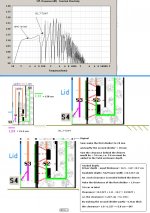
Agree, Here is a crude picture showing how to deal with a OD_T-TQWT
with clearance problem at the rear driver side:
b
")
Attachments
Hi again,
Here is what happened, I put bjorno's numbers into a spreadsheet that I had used to calculate the cross-sectional duct heights for a symmetrical tapped horn, in other words I divided the duct height by 2. Obviously, the drivers would not fit anymore. Well, haste makes waste.
I redrew the sketch to reflect bjorno's design. I hope I got it right this time. I don't think that the taper from S1 to S2 is necessary, as the stuffing in this section can be modified to suit. I guess the little extra duct below S4 would have to be modelled in AkAbak.
Regards,
Attachments
Last edited:
Hi permo,
I see no reason not to build them. If you haven't yet, take a look at DrDyna's thread: http://www.diyaudio.com/forums/subwoofers/188283-fiddling-hornresp-peerless-831759-a.html. He seems to be very pleased with the result.
You may want to redraw the enclosure, or if you want me to I can make whatever changes bjorno recommends, and add the additional dimensions.
Regards,
Hi again,
I revised the sketch with straight back, and one driver inverted (and moved over with a mounting plate). This one could be cut from one sheet of 4'x8' material (if one is willing to stick together one side panel from two pieces).
I agree, this stuff is addictive.
Regards,
I revised the sketch with straight back, and one driver inverted (and moved over with a mounting plate). This one could be cut from one sheet of 4'x8' material (if one is willing to stick together one side panel from two pieces).
I agree, this stuff is addictive
.Regards,
Attachments
Hi again,
I revised the sketch with straight back, and one driver inverted (and moved over with a mounting plate). This one could be cut from one sheet of 4'x8' material (if one is willing to stick together one side panel from two pieces).
I agree, this stuff is addictive
Regards,
Hi Oliver,
Thank you for the drawings:
They are great! I have no objection on these layouts. Is it possible to incorporate lid(s) for to attain easy access to the drivers?..and maybe the volume of damping material (= half-ways down from the S1 area at max.)
b
I cannot explain my appreciation enough!
So all of the output comes from the duct basically at S4? 4.67" X 8.63"? I am assuming that I can just wire the drivers out of phase since one is inverted?
This looks REALLY fantastic, I am going to cut some wood soon on this one. I will without question post pics of the entire project as part of my appreciation for the , way beyond any expections, efforts of the Oliver and Bjorno. All I can say is wow.
I think OAK veneer MDF Core Plywood is in order for such a great design
THANKS!! THANKS!!
Last edited:
Hi permo,
As to the wood working, as bjorno indicated, there are a number of details to be worked out. I would probably build a trial box out of MDF to see how everything fits, ultimately this calls for voidless plywood. You have to provide access to the drivers. The front driver would most easily be accessed from the front, so it needs a removable panel, and if you use the inverted top driver, you may have to add side panels. 3/4"x3/4" cleats (or battons) should work for mounting the panels, 1/8" aluminium strips can be used in the 8.625" dimension to reduce the reduction of the cross sections. You may want to give some thought to internal bracing, please, see DrDyna's thread. For a trial build I would leave one side plate loose, and attach it with screws and weather stripping. You need to be able to add damping material to the S12 section of the enclosure. It always helps to draw the location of the dividers on a side board.
I'll add an idea on how to layout the cuts on one sheet of wood. I'm busy today, but I'll try to add more dimensions to the drawing tonight.
I'll leave the question about the compression ratio to bjorno, but I think its fine.
Regards,
Attachments
Is the compression ratio acceptable on this design? Sorry for all of the questions, I am ready to start working on this project this weekend now that I have this great design. I just want to be sure I have all my bases covered.
This question has already been taken into consideration and shown in the very first simulation:
The maximum compression occurs behind the drivers and results in a < 165 dB SPL at ~19 Hz when the input is 200W Rms...
Highly unlikely that you will have problem unless you are a SPL moron and single sinus smoking testing the sub at levels above design max. at a long period ... just in order to be sure..
b
You guys have done so much to help me. Thank you so much!
so the duct opening is at S4 correct? 4.67" X 8.63"? Aside from that confirmation my only other question is regarding the distance between the ends of the internal dividers and outside panels of the enclosure. I would assume you could just use S1 and S3 for this, but I am unsure...I don't want to mess these up. I hope I am explaining correctly.
Maybe I am overanlyzing this a bit too much...so long as I get S1, S2,S3,S4 and the "L"s as close as I can to the model I should in good shape I assume. Oh, the duct as well should be accurate.
I am thinking I will buy two sheets of MDF and basically use some sort of weatherstripping for the front and sides, as opposed to an adhesive, so that I can access the drivers. Predrilled and countersunk using 2 inch wood screws, I should get a great seal.
- Status
- This old topic is closed. If you want to reopen this topic, contact a moderator using the "Report Post" button.
- Home
- Loudspeakers
- Subwoofers
- Tang Band Tang Band W8Q-1071F 8 X 12 box reccomendation