Hi folks!
I finally decided to dive into speaker building after finishing some amplifiers.
Since this is my first speaker I wanted to keep it simple. A single 30cm/12" chassis, sealed enclosure.
The chassis I want to use is a Mivoc AW 3000 ~45€
As an amplifier a symasym ~45€
I simulated with winisd with a box volume of 45l internal volume, which with boxnotes gives something around 40cm*40cm*44cm.
As I understand for sealed enclosuers, keeping specific dimensions is not really as important as for vented subwoofers. So the Shape shouldn't really matter until it gets extreme right? (as for volume winisp suggested 25l and the datasheet 40 to 55l)
A 4th order Linkwitz-Rily:
Lowpass at 175Hz,
Highpass at 19Hz to protect the cone.
A comparison with and without active filters:
Cone excursion:
SPL:
TFM:
So, this configuration is more or less the standart configuration for this driver, I know it's not exactly hifi.. but for a first this should work.
For tweaking I wanted to use dampening material in order to "simulate" a bigger enclosure.
As the graphs suggest the response is not exactly linear, is there a good way to create a more linear response (by means of active filtering etc...? Or is it simply not that important/worth the effort?
I'd be glad to hear your thoughts about this")
cheers!
I finally decided to dive into speaker building after finishing some amplifiers.
Since this is my first speaker I wanted to keep it simple. A single 30cm/12" chassis, sealed enclosure.
The chassis I want to use is a Mivoc AW 3000 ~45€
As an amplifier a symasym ~45€
I simulated with winisd with a box volume of 45l internal volume, which with boxnotes gives something around 40cm*40cm*44cm.
As I understand for sealed enclosuers, keeping specific dimensions is not really as important as for vented subwoofers. So the Shape shouldn't really matter until it gets extreme right? (as for volume winisp suggested 25l and the datasheet 40 to 55l)
A 4th order Linkwitz-Rily:
Lowpass at 175Hz,
Highpass at 19Hz to protect the cone.
A comparison with and without active filters:
An externally hosted image should be here but it was not working when we last tested it.
Cone excursion:
An externally hosted image should be here but it was not working when we last tested it.
SPL:
An externally hosted image should be here but it was not working when we last tested it.
TFM:
An externally hosted image should be here but it was not working when we last tested it.
So, this configuration is more or less the standart configuration for this driver, I know it's not exactly hifi.. but for a first this should work.
For tweaking I wanted to use dampening material in order to "simulate" a bigger enclosure.
As the graphs suggest the response is not exactly linear, is there a good way to create a more linear response (by means of active filtering etc...? Or is it simply not that important/worth the effort?
I'd be glad to hear your thoughts about this
cheers!
..For tweaking I wanted to use dampening material in order to "simulate" a bigger enclosure...
Hi, Here is a suggestion that uses damping material(not shown) for the first half of the enclosure starting at S1 in Hornresp program:
b
Attachments
Damn that looks nice...
But waaaay to big/hard for my first speaker ;-)
Thanks for the sim though, really interesting to see the differences in performance!
By chance I found the "peaking 2nd order high-pass" which looks like it can be used fairly easily to set a gain for specific frequencies. That would make 3 aktive filters in series.. what is the consens about loss of signal quality with that many filters?
cheers!
hurtz
Ok, after playing around with the filters and some reading the current data is:
- Lowpass L-R 4th, 175Hz
- Highpass L-R, 4th, 33Hz
- Peaking 2nd order Highpass 3db @ 50Hz
The lower cutoff is at 50Hz, Higher at 150Hz.
But still some questions:
- what do you think about using damping for this sealed enclosure.
- Do there have to be reinforcements in the enclosure or is the 40x40x44cm design stable enough without crossbars(?)
- For anyone who has used products from "Teufel" How do you think will this system compare with the E200/E300 Subwoofer? I don't have any useful comparison between subwoofers of different brands/makings since I only used above system for some time (until I built my own amp).
- Is the additional 10ms group-delay from the peaking filter worth the additional 10Hz in cutoff?
Groud Delay
SPL
tfm
cheers!
hurtz
- Lowpass L-R 4th, 175Hz
- Highpass L-R, 4th, 33Hz
- Peaking 2nd order Highpass 3db @ 50Hz
The lower cutoff is at 50Hz, Higher at 150Hz.
But still some questions:
- what do you think about using damping for this sealed enclosure.
- Do there have to be reinforcements in the enclosure or is the 40x40x44cm design stable enough without crossbars(?)
- For anyone who has used products from "Teufel" How do you think will this system compare with the E200/E300 Subwoofer? I don't have any useful comparison between subwoofers of different brands/makings since I only used above system for some time (until I built my own amp).
- Is the additional 10ms group-delay from the peaking filter worth the additional 10Hz in cutoff?
Groud Delay
An externally hosted image should be here but it was not working when we last tested it.
SPL
An externally hosted image should be here but it was not working when we last tested it.
tfm
An externally hosted image should be here but it was not working when we last tested it.
cheers!
hurtz
Ok, after playing around with the filters and some reading the current data is:
- Lowpass L-R 4th, 175Hz...hurtz
I never XO a sub above ~145 Hz using a LR4 LPF due to the localization issue at ~250 Hz and if used for the mains as stands: the possible Phantom hang down effect.
But still some questions:
- what do you think about using damping for this sealed enclosure.
Using a small amount of damping material doesn't hurt...
- Do there have to be reinforcements in the enclosure or is the 40x40x44cm design stable enough without crossbars(?)
I always use cross-bracing if the internal CSA is larger than ~10" x10" and if (x10" = volume) to make the enclosure as rigid as possible without overdo...
- For anyone who has used products from "Teufel" How do you think will this system compare with the E200/E300 Subwoofer? I don't have any useful comparison between subwoofers of different brands/makings since I only used above system for some time (until I built my own amp).
To be frank...I would never buy drivers from those speaker brands..
- Is the additional 10ms group-delay from the peaking filter worth the additional 10Hz in cutoff?
IMO using as peaking filter for a driver with low x-max excursion is not to design for SQ and I never allow Gldy higher than ~30 Hz to be more than the corresponding 1/f response, i.e at 50 Hz Gldy max= 1/50 = 20 mS.
b
PS: Submitting some Mivoc calculations I forgot to post and BTW the footprint of the suggested T-TQWT is a few square inch larger than the box you are simulating but the possible SQ performance would IMO be second to none.
Attachments
Last edited:
Ok, ok you have me convinced
Now you have to deal with my horn-questions ;-)
I tried to play around with hornresp but was lost after a short while... but maybe some general questions first. I can see that the horn has a very steep cutoff at 100Hz, is this a horn-specific thing?
And maybe more importantly, is there a good hornresp T-TQWT dseign/build- tutorial out there?
100l seem ok as long as its not too high to be used as a footrest below the desk
No seriously, I have a very small room at the moment so size does matter. So 40x40x120 HxDxW is more or less the maximum.
It would be great if you could help me get started on this
cheers!
hurtz
Ok, ok you have me convinced
Not my intention at all. I just found a use for your driver..Now you have to deal with my horn-questions ;-)
Horn questions? A T-TQWT is not related to a horn at first glance but more to a quarter-wave type of enclosure that is made with BP(band-pass) characteristics:
Like a TL.TQWT or a QWP that it's possible to model in Hornresp or AKAbak or partly if using MJK:'s programs.
I tried to play around with hornresp but was lost after a short while... but maybe some general questions first. I can see that the horn has a very steep cutoff at 100Hz, is this a horn-specific thing?
The T-TQWT can use an offset driver location in order to avoid that dip.
And maybe more importantly, is there a good hornresp T-TQWT dseign/build- tutorial out there?
You have to Google or do a search of this forum..I've posted a few examples...
100l seem ok as long as its not too high to be used as a footrest below the desk
A very good place to place a T-TQWT! No seriously, I have a very small room at the moment so size does matter. So 40x40x120 HxDxW is more or less the maximum.
You can estimate the build size height by dividing the length L of the airways by two and add the thickness of the wood times two, the width is the driver frame diameter + two times wood thickness and the depth would in HR be about (S1 +S4)/(driver frame width) +3 x wood thickness(internal divider included).
It would be great if you could help me get started on this
I'm not in a hurry
b
You have to Google or do a search of this forum..I've posted a few examples...
Sure, but I hoped there was THE tutorial, known by all and therefore never mentioned ;-)
cheers!
hurtz
There are many tutorials that easily can be found at the Net: On Hornresp (Search: Tutorial Hornresp) ..or trying to circumvent the deeper knowledge(patience) required for a successful speaker design.
An example:
Easy Horn Spreadsheet for Dummies - AVS Forum
PS:I will not reply to any question concerning this spreadsheet.
b
An example:
Easy Horn Spreadsheet for Dummies - AVS Forum
PS:I will not reply to any question concerning this spreadsheet.
b
Some enlightening hours later...
Thanks again for the sim this was a great help, so some new questions
1. Shouldn't L12 and L34 always be the same size to prevent overlapping of the enclosure?
2. In the loudspeaker-wizard, I try to calculate cone excursion but somehow when using Pmax instead of Eg, the cone excursion starts to change its shape rather than its amplitude. As Eg is dependant on Pmax and impedance I don't quite understand why it is doing this. Also Pmax to reach maximum cone excursion is really low... Is Pmax the acoustical output power???
cheers!
hurtz
P.s. I expected L23 to be much more critical for frequency response than the simulation told me, but I guess this is a result of the low frequencys. Also it seemed quite impossible to to raise the higher cutoff frequency to 100Hz without drastically loosing on low frequency response.
1. Shouldn't L12 and L34 always be the same size to prevent overlapping of the enclosure?
No
2. In the loudspeaker-wizard, I try to calculate cone excursion but somehow when using Pmax instead of Eg, the cone excursion starts to change its shape rather than its amplitude. As Eg is dependant on Pmax and impedance I don't quite understand why it is doing this. Also Pmax to reach maximum cone excursion is really low... Is Pmax the acoustical output power???
There in no reason to ever calculate Pmax as the T-TQWT is displacement limited only for low frequencies.
Pmax is dependent on Eg and the impedance at the specific frequency used when calculating, not the opposite!
P.s. I expected L23 to be much more critical for frequency response than the simulation told me, but I guess this is a result of the low frequencys. Also it seemed quite impossible to to raise the higher cutoff frequency to 100Hz without drastically loosing on low frequency response.
Impossible? No, But you always trade Power-handling with BW.Look at the submitted example:
b
Attachments
Hmm I see, thanks...
I actually had the wrong design in mind.
I'd like to know what you think of the attached design, SPL is a bit higher at 100HZ, but not too much and the response is a little more flat. Eg is at 13.5 => 46W in 4Ohm
A question on cone excursion vs. simulation though, my research suggests that the response will be a bit flatter than the simulation due to resonance of the enclosure (and general not ideal physics). Now to keep the driver safe, will it be the same with the excursion? Or how should the safety margin be chosen?
I wanted to include a simple vu/power-meter to tell me when the maximum power exceeds driver capabilities. Also due to the low power demands of the T-TQWT I think I will rather use a LM3886 with 80VA toroidal than the symasym.
Thanks and cheers!
hurtz
Attachments
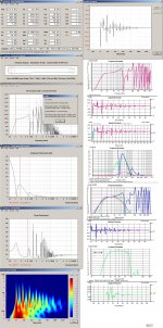
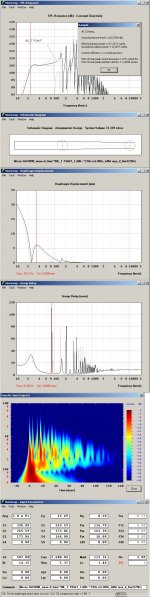
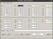
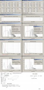
Finally got time to make the screenshots,
I've changed some more and sacrificed some SPL for flatness of frequency response. Since I'm "only" using it for movies and a party a few times a year an average above 100db should be more than enaugh I think.
So let me know what you think of the design and if I missed anything vital!
cheers!
hurtz
I've changed some more and sacrificed some SPL for flatness of frequency response. Since I'm "only" using it for movies and a party a few times a year an average above 100db should be more than enaugh I think.
So let me know what you think of the design and if I missed anything vital!
cheers!
hurtz
Attachments
-
mivoc_v2.txt408 bytes · Views: 27
-
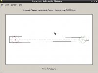 schem.jpeg27.8 KB · Views: 22
 -
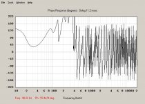 phase.jpeg55.6 KB · Views: 28
 -
 main.jpeg63.2 KB · Views: 26
 -
 impspec.jpeg50.2 KB · Views: 21
 -
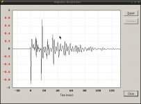 impresp.jpeg39 KB · Views: 12
 -
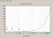 elimp.jpeg37.9 KB · Views: 119
 -
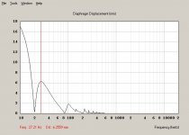 displ.jpeg38 KB · Views: 118
 -
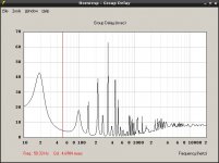 delay.jpeg49.3 KB · Views: 117
 -
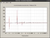 acimp.jpeg46 KB · Views: 134
post#13:
See the two * here-below.( Advises to a T-TQWT design using HR TH modeling recommendations (observations) would IMO lend to an apples to oranges comparison)
HR cannot predict the superior resulting performance(IR,Gldy FR smoothness and so on....) of a stuffed T-TQWT/T-QWP when comparing with a TH, but this can easily partly be shown, by using quarter-wave programs like MJK:s.
Your first HR simulation in post#13 would work but with a 2 dB lower in-band SPL if compared with the one I posted.
I targeted a single folded T-TQWT with your driver and to use a smaller enclosure with an unusual(larger) compression ratio,that has to be stuffed with less amount of damping material than a normal T-TQWT would be:
Therefore the 'non peaking' of the lower FR corner as I always try to use an optimum amount of damping material but always fill ~ half of the enclosure counted from the largest CSA.
*You've probably read that in HR shown peaks doesn't matter but I have an entirely different opinion:
Based on measurement and listening to single folded TH:s + T-TQWT:s and T-QWP:s:
A single folded TH that isn't stuffed with damping materials will preserve the in HR shown peaks to a larger degree than if multi-folded* but would still sound IME very boxy/resonant and is not suitable for home HT or music unless an advanced parametric EQ + Signal delay units(often needed) are in use but may be more successful for outdoor/ large venues Live/PA reinforcement as the 'Low-Fidelity' artifacts would be more or less masked.
Your design show a maximum input of 43.5 W before exceeding x-max at ~ 28.5 Hz that if provided a suitable HPF is in use to protect otherwise evidently over-excursion that would occur at lower frequencies.
Then a maximum operating power level of -3dBW is a good choice to not exceed for SQ reasons, that is ~22W. 22W at 4 Ohm → 9.38V Rms=Peak_13.27 V could be used for an comparator input trigger voltage to indicate beginning of an overload or a minimum voltage acting on a soft limiting circuit that goes hard limiting or into complete mute mode if reaching ~18.65 V peak.
When using a single LM3886 and a typical 4 Ohm load: Choose a transformer with a secondary RMS Voltage <= 2x20.
Agree !00dB/(2x Pi) or if the sub is placed near a room corner the corresponding SPL is more than 110 dB or max. ~161 dB internal SPL at the enclosure section within the S2-S4 areas, a quite easy load for a T-TQWT to cope with as this occurs only at a very low frequency (~19 Hz).
I noticed a problem conserning the very high Sd/ port ratio, that in my example is around 3:1(~optimal if not larger ratio) but for your last simulation the ratio is ~9:1.
For sure this will lend to annoying port chuff's at higher SPL.
b
..my research suggests that the response will be a bit flatter..
See the two * here-below.( Advises to a T-TQWT design using HR TH modeling recommendations (observations) would IMO lend to an apples to oranges comparison)
HR cannot predict the superior resulting performance(IR,Gldy FR smoothness and so on....) of a stuffed T-TQWT/T-QWP when comparing with a TH, but this can easily partly be shown, by using quarter-wave programs like MJK:s.
Your first HR simulation in post#13 would work but with a 2 dB lower in-band SPL if compared with the one I posted.
I targeted a single folded T-TQWT with your driver and to use a smaller enclosure with an unusual(larger) compression ratio,that has to be stuffed with less amount of damping material than a normal T-TQWT would be:
Therefore the 'non peaking' of the lower FR corner as I always try to use an optimum amount of damping material but always fill ~ half of the enclosure counted from the largest CSA.
*You've probably read that in HR shown peaks doesn't matter but I have an entirely different opinion:
Based on measurement and listening to single folded TH:s + T-TQWT:s and T-QWP:s:
A single folded TH that isn't stuffed with damping materials will preserve the in HR shown peaks to a larger degree than if multi-folded* but would still sound IME very boxy/resonant and is not suitable for home HT or music unless an advanced parametric EQ + Signal delay units(often needed) are in use but may be more successful for outdoor/ large venues Live/PA reinforcement as the 'Low-Fidelity' artifacts would be more or less masked.
..Now to keep the driver safe, will it be the same with the excursion? Or how should the safety margin be chosen?..
Your design show a maximum input of 43.5 W before exceeding x-max at ~ 28.5 Hz that if provided a suitable HPF is in use to protect otherwise evidently over-excursion that would occur at lower frequencies.
Then a maximum operating power level of -3dBW is a good choice to not exceed for SQ reasons, that is ~22W. 22W at 4 Ohm → 9.38V Rms=Peak_13.27 V could be used for an comparator input trigger voltage to indicate beginning of an overload or a minimum voltage acting on a soft limiting circuit that goes hard limiting or into complete mute mode if reaching ~18.65 V peak.
When using a single LM3886 and a typical 4 Ohm load: Choose a transformer with a secondary RMS Voltage <= 2x20.
..I've changed some more and sacrificed some SPL for flatness of frequency response. Since I'm "only" using it for movies and a party a few times a year an average above 100db should be more than enaugh I think..
Agree !00dB/(2x Pi) or if the sub is placed near a room corner the corresponding SPL is more than 110 dB or max. ~161 dB internal SPL at the enclosure section within the S2-S4 areas, a quite easy load for a T-TQWT to cope with as this occurs only at a very low frequency (~19 Hz).
I noticed a problem conserning the very high Sd/ port ratio, that in my example is around 3:1(~optimal if not larger ratio) but for your last simulation the ratio is ~9:1.
For sure this will lend to annoying port chuff's at higher SPL.
b
Attachments
Last edited:
Hmm I see, thanks for the explanations!
I have the distinct feeling that your design in post 2# is as close as it gets to the optimum for this driver...
The peak at 85Hz seems to be dealt with by using a filter, what program did you use to simulate the LR-filtering on the HR response?
Also I did think about the multi-folding, the form factor seems a bit more convenient. I also looked at some tutorials for this, it doesn't seem overly complicated once the basic design parameters are known.
Speaking of the basic design parameters, can you just do them by hand, lets say 40cm width for easy mounting of the driver and then just calculate the rest? Or does it require more math
cheers!
hurtz
..I have the distinct feeling that your design in post 2# is as close as it gets to the optimum for this driver...The peak at 85Hz seems to be dealt with by using a filter, what program did you use to simulate the LR-filtering on the HR response?..
Thats the one I would follow too..You're right if the peak is small it will be swamped by the LPF.I always try to use tools of the trade to show manipulated HR exported data: Here the easy to use freeware HOLMimpulse program.
..Also I did think about the multi-folding, the form factor seems a bit more convenient. I also looked at some tutorials for this, it doesn't seem overly complicated once the basic design parameters are known...
It's up to your intension but sometimes a tedious work that I assign to the DIY'r to do and the outcome of FR from using multi-folds can be quite different as a series of equivalent LPF is introduced from the bends causing unpredictable in-band/off-band response. A POC is the only way to know..
..Speaking of the basic design parameters, can you just do them by hand, lets say 40cm width for easy mounting of the driver and then just calculate the rest? Or does it require more math..
Of course, I usually start with the driver frame width(+ a few mm:s) and calculate the required CSA that can accommodate the driver with a suitable rear clearance behind the driver magnet for the CSA= S2 in HR.
If to close to the Wood in use, I start to increase the Driver baffle thickness before alter other enclosure dimensions...
b
The S2 seems to narrowly fit.
Driver frame width is 31.5cm and has a depth of 12.4cm. So a total width of 35cm for the enclosure makes that [S2=489cm²] 489cm²/35cm=13.97cm.
When drawing it, the cone of the driver is "overlapping" the opening at S4, that doesn't seeem right. But since L34 is only 10cm..
Also I think I have to go with a multi-fold or smaler design since there is now way I can fit in the ~145*35*19cm (the 145cm especially...)
Sadly holmimpulse doesn't work in linux so I have to delay the filter part until I can grab hold of a windows machine for a few hours...
thanks & cheers!
hurtz
P.s.
Ok erase the drawing part.. made an error >.<
If there is a problem with driver clearance, never add more than a few mm to the driver frame width when calculating the resulting section depth from the suggested S2 CSA.
Step by step:
b
Attachments
- Status
- This old topic is closed. If you want to reopen this topic, contact a moderator using the "Report Post" button.
- Home
- Loudspeakers
- Subwoofers
- Design check of a simple <100€ sub