So don't expect miracles as i know it isn't one  but you gotta start somewhere ! Why that driver ? Well i happened to be looking at their catalogue right before, & it "seemed" doable based on the TH criteria thread etc.
The mash up was a one octave design from 40Hz - 80Hz & imagining for eg 12dB filters - HP @ 35Hz & LP @ 85Hz
Please feel to tear it apart, critique away, & point out etc how you might improve it, & my HR design process in general
TIA
but you gotta start somewhere ! Why that driver ? Well i happened to be looking at their catalogue right before, & it "seemed" doable based on the TH criteria thread etc.The mash up was a one octave design from 40Hz - 80Hz & imagining for eg 12dB filters - HP @ 35Hz & LP @ 85Hz
Please feel to tear it apart, critique away, & point out etc how you might improve it, & my HR design process in general
TIA
Attachments
Hi Zero D,
You might want to check your T/S parameters against the current factory values. Also, when in the Edit mode you can double click on Sd, and you'll get to a pop-up window with the driver T/S values. That way you can check for entry errors. I usually input factory values, but use Hornresp to recalculate, i.e.: enter Sd, then double click on Cms, etc.
By setting Ang to 0.5 x Pi you'll get a possibly unrealistically high output. For comparison I like to use 2.0 x Pi. I also like to use Eg=2.83 for comparison purposes.
When using the Wizard start by setting S2 and S4 to Auto (double-click the red labels), then use the sliders to get you in the ball park. Once you have something that looks reasonable you can set them back to manual.
I'll attach a Hornresp export file w/ your choosen driver (using recalculated factory T/S) in which I added a throat chamber, and used a short L12. Just something to play with.
Attachments
Last edited:
@ m R g S r
Yes somethings wrong
@ tb46
Hi, thanks Very much for doing that for me, & the useful info you provided too. I appreciate it as it All helps I'm going to spend some time experimenting with it, & then post back
@ bjorno
Hi, thanks for the info & screenie Looks interesting.
Yes somethings wrong
@ tb46
Hi, thanks Very much for doing that for me, & the useful info you provided too. I appreciate it as it All helps
I'm going to spend some time experimenting with it, & then post back @ bjorno
Hi, thanks for the info & screenie
Looks interesting.1/2/3 etc
@ tb46
Had a bit more time to play I wonder if you're seeing what i'm seeing ? I havn't altered Anything you inputted etc as yet.
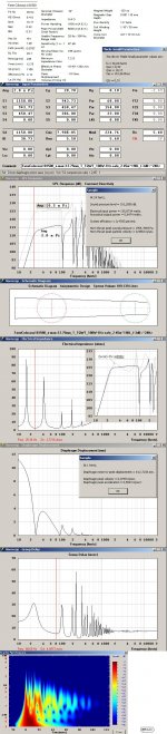
1 - The displacement is 50% better @ 1 pi =
2 - The max power "seems" severely limited for a 1500w 12.7 Xmax driver ?
3 - The response gets lumpy at anything over 0W ?
I fully appreciate that you did this as a test for me & it isn't a production finished etc design. But to try & gain a deeper insight into using HR, i'd like to know your thoughts on the above.
TIA
@ tb46
Had a bit more time to play
I wonder if you're seeing what i'm seeing ? I havn't altered Anything you inputted etc as yet. 1 - The displacement is 50% better @ 1 pi =
2 - The max power "seems" severely limited for a 1500w 12.7 Xmax driver ?
3 - The response gets lumpy at anything over 0W ?
I fully appreciate that you did this as a test for me & it isn't a production finished etc design. But to try & gain a deeper insight into using HR, i'd like to know your thoughts on the above.
TIA
Attachments
Hi Zero D,
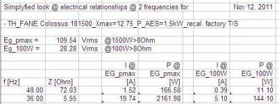
You found some interesting graphs that I normally don't use, and you may want to ask David McBean about them. I'm assuming, that when Pmax is engaged the program calculates against this value, the "lumpy" response looks that way as at constant power the SPL response becomes a function of the impedance. When Eg is held constant (this means the applied power varies inversely to the impedance), the SPL response smoothens out. Sliding Xmax to 0.0 causes the graph to display the default response that you get when you hit Calculate in the Input screen.
For displacement I look at the Diaphragm Displacement window (after clicking on Calculate) after setting the input power under Eg (double-click Eg).
For limits I look at the Maximum SPL Tool from the SPL Response window. E.g.: set Maximum driver input power in watts to: 1500, and Maximum diaphragm displacement in mm to: 12.5.
Regards,
Hi there ZeroD: TH's are severly limited at "low" frequency by Xmax. So manually set Eg to a value... try 28v, then go to displacement screen and examine the graph. If dispacement is still below 12.7mm, return to input screen and edit Eg to a higher value...etc...untill you reach Xmax, from the displacement graph, you can see the frequency where you will need to CUT OFF the low frequency to get more driver power without exceeding Xmax. If you really want to reach flat to 28hz low corner (F3 probably 22/23hz), you probably need to revise the input selections or redesign completely. HR can do a fine job, but it usually takes some time to get to your design limits: low corner,
F3, power needed, Xmax available, band width desirable, size/weight you can tolerate, driver(s) cost. ...regards, Michael
F3, power needed, Xmax available, band width desirable, size/weight you can tolerate, driver(s) cost. ...regards, Michael
Physical size?
These TH sims seem quite small at 220 Litres (Zero D) and 189 Litres (Bjorno)
So small in fact that I could see there could be difficulty in fitting a 18" driver.
Dimensions of the Fane Driver are 45.7 cm across flats and 22.5 cm deep
45.7 X 22.5 = 1028.25 cm sq - The cross sectional areas in the sims are far smaller than this value.
Agree There's a short of required CSA but this can easily be fixed when in a single fold: Double or triple the thickness(0.75"= ~19 mm) of the internal divider.
b
Originally Posted tb46
You found some interesting graphs that I normally don't use, and you may want to ask David McBean about them.
I will
For displacement I look at the Diaphragm Displacement window (after clicking on Calculate) after setting the input power under Eg (double-click Eg).
On doing that it looks fine, but using the graphs i did, not very
I'm hoping DB will clarify where i'm probaly going wrongFor limits I look at the Maximum SPL Tool from the SPL Response window. E.g.: set Maximum driver input power in watts to: 1500, and Maximum diaphragm displacement in mm to: 12.5.
Doing that i get limited to 100W @ Xmax ?
I'll post back after i hopefully get to the bottom of it
Thanks
@ j.michael droke
Hi, Thanks for your info
Hopefully my above post explains more about the issues i'm experiencing.@ Xoc1
I agree it's quite "compact"
Thanks for the heads up @ bjorno
Good suggestion, Thanks
Hi there ZD: I ran your input data through HR and found the following results:
input Fane 18500 Fs=36, Re=5.4, Qt=0.31, Qm=10.17, Qe=0.31, Vas=151.06L and:
at 21hz, 123.7db, 12.2mm disp., 58v and 130.6db 26hz to 83hz +3.6db -2.0db..comment:
(reasonably close to your HR) (not flat at +3.6 -2.0) and:
a filter cutoff needed protecting the Fane from exceeding 12.7mm displ. below21hz
I do not see that you are in error for HR, however others here have commented on the size and applicability to fit the Fane in to the folds....regards, Michael
Hi Zero D,
This is a follow-up to my above Posts #3 and #7, as well as to the questions you asked in the Hornresp thread, Post #2444: http://www.diyaudio.com/forums/subwoofers/119854-hornresp-245.html
Hope this helps.
Regards,
This is a follow-up to my above Posts #3 and #7, as well as to the questions you asked in the Hornresp thread, Post #2444: http://www.diyaudio.com/forums/subwoofers/119854-hornresp-245.html
Hope this helps.
Regards,
Attachments
- Status
- This old topic is closed. If you want to reopen this topic, contact a moderator using the "Report Post" button.
- Home
- Loudspeakers
- Subwoofers
- My First TH design