I've been doing a dangerous thing of late - thinking. I've been reading around and trying to understand better the purpose and function of the various "impedance matching" enclosures that are popular in the DIY communities of late. (TQWT, Rear loaded horns, tapped horns, etc.)
It seems one of the base principles of these enclosures is to match the 'physical impedance' of the driver to that of open air in a room. Is this incorrect?
Horns taper from a small cross-sectional area to a large one, very similar to the taper profiles exampled in microwave engineering books for microstrip transmission lines. There are many topologies for matching impedance (real valued anyway, I have no idea how to make an air-fluid inductor or capacitor haha) in high frequency electrical systems.
The one I would like to discuss is that of the Chebyshev N-section impedance transformer. It is an equal-ripple bandpass type that consists of N quarter wavelength sections (of Fc) whose characteristic impedance step from Z0 to ZL according to a Chebyshev profile (you can easily look this up).
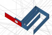
If (as with horns) an increasing throat area is the "impedance change" of the line, a 4- section transformer with ripple gamma=.05 and Fc at 60Hz, should have a band range from appx 20Hz-100Hz +-3dB.
Of course with a quarter wavelength in air @60Hz being around 143cm, the entire structure is very large. For the case I am playing with, it's nearly 14cuft of airspace in the entire enclosure!
I attached a quick drawing and a very sloppy spreadsheet if anyone is interested.
This thread will serve as a live journal of my research and experimentation. Comments/feedback are encouraged!
It seems one of the base principles of these enclosures is to match the 'physical impedance' of the driver to that of open air in a room. Is this incorrect?
Horns taper from a small cross-sectional area to a large one, very similar to the taper profiles exampled in microwave engineering books for microstrip transmission lines. There are many topologies for matching impedance (real valued anyway, I have no idea how to make an air-fluid inductor or capacitor haha) in high frequency electrical systems.
The one I would like to discuss is that of the Chebyshev N-section impedance transformer. It is an equal-ripple bandpass type that consists of N quarter wavelength sections (of Fc) whose characteristic impedance step from Z0 to ZL according to a Chebyshev profile (you can easily look this up).
If (as with horns) an increasing throat area is the "impedance change" of the line, a 4- section transformer with ripple gamma=.05 and Fc at 60Hz, should have a band range from appx 20Hz-100Hz +-3dB.
Of course with a quarter wavelength in air @60Hz being around 143cm, the entire structure is very large. For the case I am playing with, it's nearly 14cuft of airspace in the entire enclosure!
I attached a quick drawing and a very sloppy spreadsheet if anyone is interested.
This thread will serve as a live journal of my research and experimentation. Comments/feedback are encouraged!
Attachments
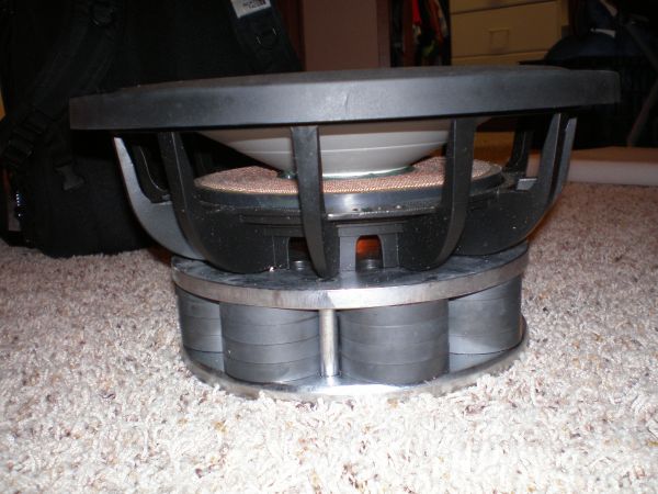
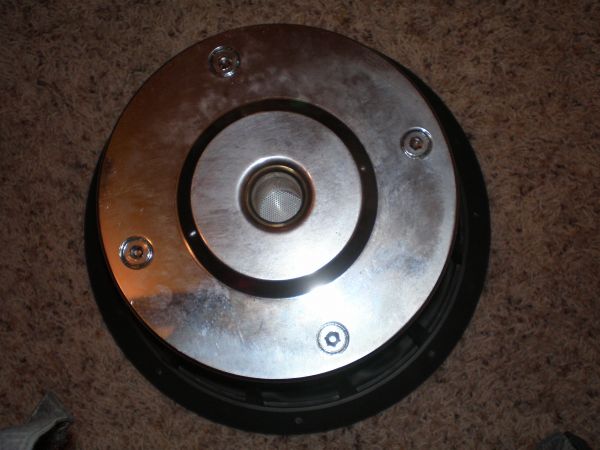
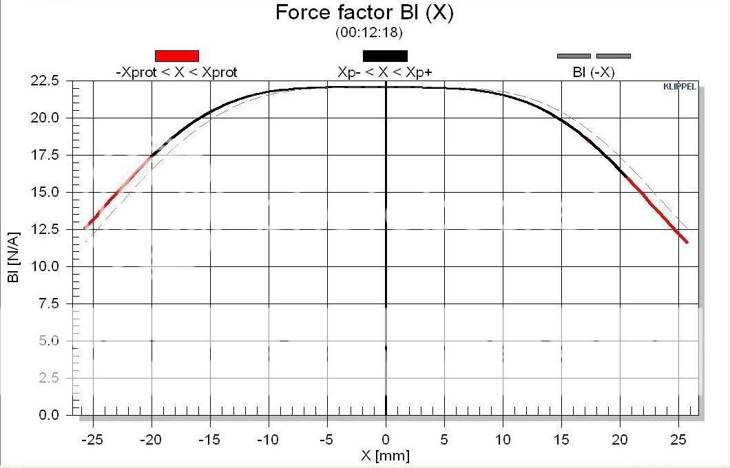
As a reference, this is the woofer I am designing the initial enclosure around:
Fs 25.21 Hz
Qms 4.748
Vas 41.71 L
Cms 121.9 umN
Mms 326.8 g
Rms 10.91 mohms
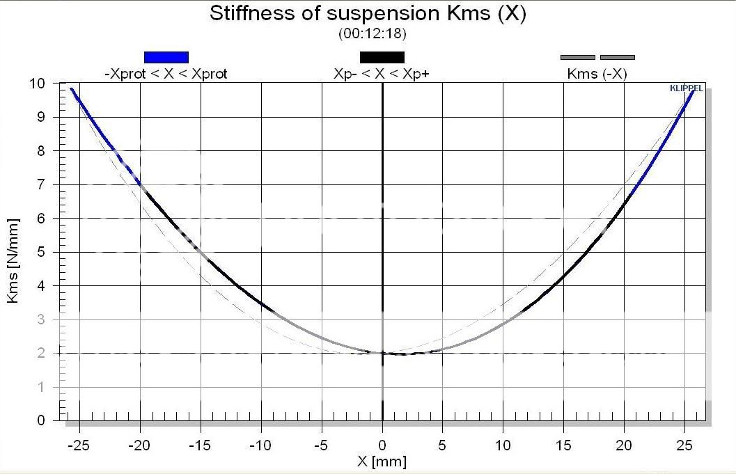
Xmax 23 mm
Xmec 32 mm
Dia 25 cm
Sd 491 sq. cm.
Vd 1.129 L
Qes 0.383
Re 3.6 ohms
Le 1.319 mH
Z 4 ohms
BL 22.07 NA Tm
Pe 1000w (up to)
Qts 0.354
no 0.169
SPL 84.3 1W1m
SPL 87.89 2.8V1m
(hotlinked from Mark Fantini at ecoustics.com)
Fs 25.21 Hz
Qms 4.748
Vas 41.71 L
Cms 121.9 umN
Mms 326.8 g
Rms 10.91 mohms
Xmax 23 mm
Xmec 32 mm
Dia 25 cm
Sd 491 sq. cm.
Vd 1.129 L
Qes 0.383
Re 3.6 ohms
Le 1.319 mH
Z 4 ohms
BL 22.07 NA Tm
Pe 1000w (up to)
Qts 0.354
no 0.169
SPL 84.3 1W1m
SPL 87.89 2.8V1m
(hotlinked from Mark Fantini at ecoustics.com)
Last edited:
Since I was too late to getting back to edit the previous post, I'll add another entry.
I wanted to discuss the driver selection. This driver is one marketed toward car audio, and is no longer readily available. I apologize for this, especially if the concept turns out to work, it would be needed to find a new driver. The device is the "DIYMA 12R".
I purchased a few of these when npdang first started selling them on the diyma forum. (I'm sure you're all aware of its existence)
I've always been fairly impressed with its performance in a standard sealed box. I had tried many many iterations of boxes ranging from .5cuft to 1.5cuft with various levels of stuffing. I forget where I ended up, but it works OK in my car, good enough to have in there for 3 years, but I've never really considered doing anything else with it till now.
The driver has a very flat BL vs +-15mm x(t). It has a relatively high static BL product as well. This seems the trend for modern woofers - large displacements to move air, instead of efficient couplings.
This driver would not be suited for a typical front or rear loaded horn for the simple fact that the cones have been renowned for self destructing at high pressure levels!
The super high compression level would likely destroy the thin aluminum driver at even moderate excursion (just a theory, I have no proof of this).
The Qms and Qts are favorable for the type of tuned chamber coupling that will be used. The only issue is the VAS, which is higher than I would like. (and low efficiency, but that's the point of this enclosure).
The Chebyshev enclosure utilizes N lam/4 sections (mine N=4), with the initial chamber throat appx equal to the surface area of the driver. Each successive section increases as 1/Cheb(N) as shown in the spreadsheet (will clean it up later).
I have not settled on how to couple the driver to the initial throat size. I'll likely change from the rough sketch above to use a short linear taper (sure a Klopfenstein taper would be best, but I don't have the skill to make one!) with total enclosed volume = Vd.
Ideally I would like it to behave like a back loaded horn, but if I end up destroying a drive due to the pressure differential, I'd investigate front loading with a tuned sealed rear chamber.
The cone control and compression levels will be greatly less than that of traditional horn designs, and ergo the efficiency. However having a flat response to 20Hz with minimal magnitude ripple in the passband is more important to me than absolute efficiency increase.
Last edited:
What's your target ripple?
I'm guessing that ZroomP) = ~416-420 Pa·s/m
how are you calculating the time/temperature gradient within the T line?
You have intrigued me...
If I'm not completely mistaken the passband ripple will be approximately 0.87dB.
===================
I do not yet have an accurate model to test my theory. I am still in the investigative phase of this project. The current "model" is simply an adaptation from a white paper I read recently.... I will post what I'm referring to if I can recall which is was. Anyway their electrical description in terms of relative impedances gave a short formula to normalize Th-Sm parameters into a "physical impedance" taking into account driver mass, resonance, mechanical Q, etc. They also labeled air in a general at STP as "near 8 Physical Ohms". Their model, not mine. So the "impedance match" comes from matching a port or line cross sectional area that the driver is coupled to that is "equal" to the driver's physical impedance (very large ~80-120 ohms for most speakers) and matching it to the relatively low 8 ohm room impedance. The "matching" is done according to the Chebyshev impedance matching transformer coefficients. Microwave Engineering by M. Pozar describes this, I'm sure a Google search will reveal the same to you. For a 4 section, the relative coefficients are
10 6.3578 3.8728 2.0657 1.2583
1
for a 10:1 impedance mismatch (driver being 10 times the impedance of the airspace).
So an "impedance match" of my current model takes in no way the pressure differential at the step discontinuities into account, except in the way that the waveguide electrical model does already. It does not take into account any temperature rise within the chambers as the air is compressed by the pressure waves. I realize it is not a perfect isothermal process, I just don't yet have the knowledge to include these effects.
===========================
I look forward to reading more information on the models and equations hornresp and M. King's mathcad for their respective domains. I'd rather develop this within a scientific manner, and not just take a guess and cut up 3 sheets of BB
:3
Cheers
Last edited:
Since I was too late to getting back to edit the previous post, I'll add another entry. ..... The device is the "DIYMA 12R".
The Chebyshev enclosure utilizes..., with the initial chamber throat appx equal to the surface area of the driver.
I have not settled on how to couple the driver to the initial throat size. I'll likely change from the rough sketch above to use a short linear taper (sure a Klopfenstein taper would be best, but I don't have the skill to make one!) with total enclosed volume = Vd.
Ideally I would like it to behave like a back loaded horn, but if I end up destroying a drive due to the pressure differential, I'd investigate front loading with a tuned sealed rear chamber. /QUOTE]
Hi there: Great spread sheet. Followed everything, except the calculation of the "surface area of the driver= 2164 cm^2? Should this be the pistonic area measured as Sd? (which the manufacturer was quoted as 491cm^2) ...regards, Michael
Sorry it took so long to get back to you! Work has been busy this week.
It looks like I flubbed that number before uploading. I did mean to use Sd in that calculation.
Looking back, it seems unrealistic now, as Sd/10 is a tiny tiny area, yielding a 10:1 compression ratio (using horn terms) at the "throat".
I have some more thinking to do. This is in no way a good plan/model/design.
Looking back, it seems unrealistic now, as Sd/10 is a tiny tiny area, yielding a 10:1 compression ratio (using horn terms) at the "throat".
Yeah, the best compression drivers are around/at 10:1, making them so well damped that they can be safely used [within reason] with/without a rear chamber. Using Prof. Leach's math to do the equivalent for this driver results in a ~5-132 Hz BW and a ~6.63 compression ratio, so a poor choice indeed for proper impedance matching in a typical HIFI/HT app.
GM
- Status
- This old topic is closed. If you want to reopen this topic, contact a moderator using the "Report Post" button.
- Home
- Loudspeakers
- Subwoofers
- Hypothesis? 4-section Chebyshev enclosure