It seemed to me that if one didn't really need all of the efficiency gain of a full blown horn subwoofer then a TL might have some advantages. My thinking is that one would gain a size and delay advantage with the nominally quarter wave path length over an equivalent FLH.
With that in mind I toyed a bit with Hornresp using the parameters of a salvaged Hammond organ 12" driver. My assumption was that one would model this much like a BLH, That is with rear chamber volume and length set to zero and with a reverse tapered conical segment. I used the XLS spreadsheet that I found at the quarter wavelength site to get some starting numbers and ran some simulations.
Over all the results look good using the combined response tool. I used a little over 3x SD for the driver end with the terminus at half that area with the length a bit longer than the spreadsheet suggested (around 325cm IIRC). Response was sloping down from 80Hz to 20Hz at about 5 or 6dB/8va (loosely coupled room gain should restore that) and then dropping rapidly just below 20Hz.
The thought occurred to me to use a push pull orientation with two drivers. Of course it is simple in the case of an end driven line to just put the two drivers side by side with one inverted (and wired "out of phase") but this cancels only even order harmonics and unlike the 12pi front loaded horn there is no acoustical low pass on the direct radiator portion of the output so odd order harmonics would now dominate.
To address this one could I presume use a slot loaded push pull arrangement where the manifold itself would provide an acoustical low pass of sorts to help damp the odd order harmonics. Would you agree?
To do this I assume one would build the manifold with a throat connecting it to the end of the line. However I am not sure how one would model this kind of thing in hornresp.
To further complicate things I understand that it is generally better to tap into the line about 1/3 of the way from the closed end. With a normal mounting this is not hard to model in horn response using the side mount tool but when it is a manifold and not a driver mounted at this position it is less clear to me.
Now one further question regarding folded TL implementation. If you make an "S" shaped line with the driver mounted at the fold closest to the closed end does it matter whether the driver is aligned with the first segment (i.e. firing into the closed section), the second segment or split between the two?
Appreciate any input.
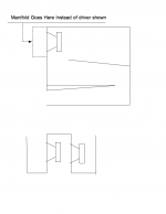
To make clear what I am talking about...
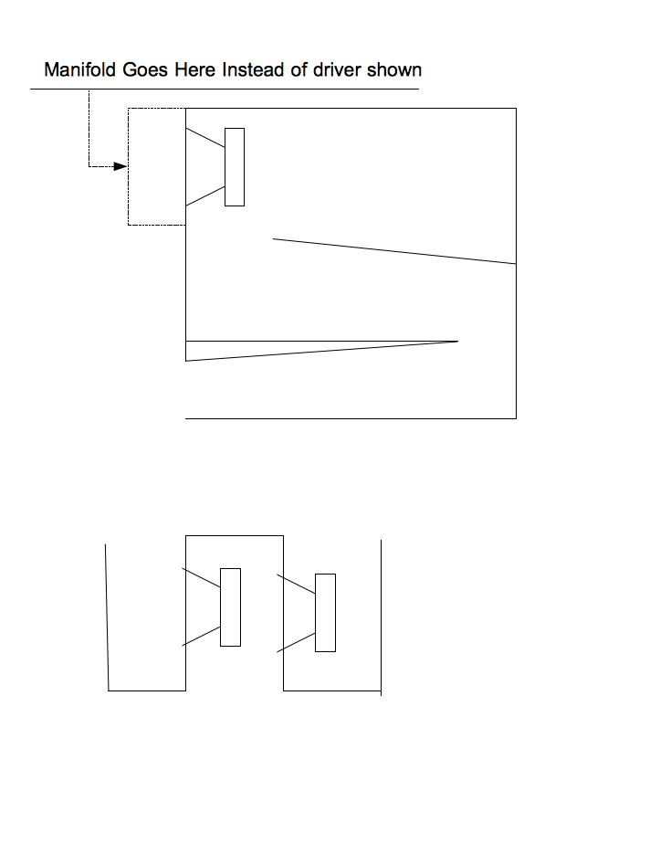
The manifold would replace the single driver shown in the TL enclosure. I presume that the center plenum of the manifold would be the proper side to have on the outside since that is where the LP filtering would occur. In real life I imagine I would find a way to build it in to the cabinet so there was no appendage.
Also I would guess that for 12" drivers with SD of around 500 cm^2 that the opening of the plenum should be somewhere between 500 - 1000 cm^2.
Attachments
A short manifold plenum as you propose probably won’t have much acoustical low pass effect below around 160-200 Hz , so won’t reduce third harmonic distortion below 53-66 Hz or so.The thought occurred to me to use a push pull orientation with two drivers. Of course it is simple in the case of an end driven line to just put the two drivers side by side with one inverted (and wired "out of phase") but this cancels only even order harmonics and unlike the 12pi front loaded horn there is no acoustical low pass on the direct radiator portion of the output so odd order harmonics would now dominate.
To address this one could I presume use a slot loaded push pull arrangement where the manifold itself would provide an acoustical low pass of sorts to help damp the odd order harmonics. Would you agree?
That said, the third harmonic of say, 100 Hz (300 hz) is more objectionable than the third harmonic of 53 Hz, (159 Hz), so the plenum idea is worth pursuing.
Lining the plenum with felt may increase the effectiveness of the LP, and lower the LP frequency.
- Status
- This old topic is closed. If you want to reopen this topic, contact a moderator using the "Report Post" button.