cone correction
Hi Djim,")
I went back to the start of conversations on cone corrections at post 484,and read it all again.
So is the triangle shape the preferred way to go ?
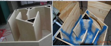
I can still make that change so I am going to fit braces and other touch ups before I close the box ,
The drawings look like the tip of the triangle needs to be at the baffle level,and the side pieces create a slot ,I could not glue these pieces just use screws and use them to tune it ,then glue it in and make it permanent,LOL.
I am not in a hurry to finish ,I hope to make them the best I can ,I wish I was smarter with speaker science,lol
Thanks for your help!
NS
Hi Djim,
I went back to the start of conversations on cone corrections at post 484,and read it all again.
So is the triangle shape the preferred way to go ?
I can still make that change so I am going to fit braces and other touch ups before I close the box ,
The drawings look like the tip of the triangle needs to be at the baffle level,and the side pieces create a slot ,I could not glue these pieces just use screws and use them to tune it ,then glue it in and make it permanent,LOL.
I am not in a hurry to finish ,I hope to make them the best I can ,I wish I was smarter with speaker science,lol
Thanks for your help!
NS
Hi noSmoking,
Martin (Xoc1) seems to be working on a new design for the Xoc1-TH18 with cone correction. It wouldn't surprise me if that would lead to a new internal structure.
I am not sure but it looks like you already have made some sheet cuts so changing to a new internal lay-out will be difficult (or you need to spend some extra on new sheets).
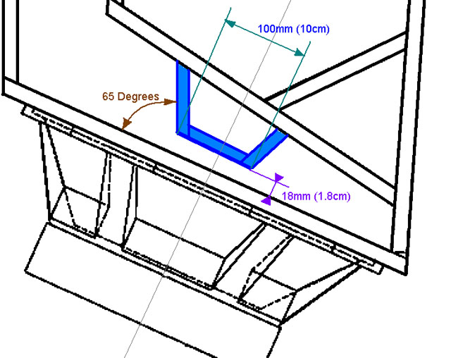
For Crescendo I suggested something that really follows the structure of the cone. This is probably not necessary as the main goal of cone correction is to correct the position of the pressure zone (there where the horn-path is most narrow) towards the centre of the driver or towards the position as in the sim. For the strongest drivers it doesn't matter so it is best positioned as the sim suggests but for less capable drivers I believe it is best positioned above the centre of the driver.
A more simplistic way to do that is shown in the picture. The "stub" is going from one side to the other, so it expands of the entire width of the cab. As you can see it is just a little out of the centre of the driver (somewhere between 0.5 to 1.5cm). I suggest to use at least two braces in the "stub" cavity. You can also make the whole stub from one solid piece to increase stiffness (but is more heavy of course).
Like ODougbo already said, don't forget to fill up your cavities....
Martin (Xoc1) seems to be working on a new design for the Xoc1-TH18 with cone correction. It wouldn't surprise me if that would lead to a new internal structure.
I am not sure but it looks like you already have made some sheet cuts so changing to a new internal lay-out will be difficult (or you need to spend some extra on new sheets).
For Crescendo I suggested something that really follows the structure of the cone. This is probably not necessary as the main goal of cone correction is to correct the position of the pressure zone (there where the horn-path is most narrow) towards the centre of the driver or towards the position as in the sim. For the strongest drivers it doesn't matter so it is best positioned as the sim suggests but for less capable drivers I believe it is best positioned above the centre of the driver.
A more simplistic way to do that is shown in the picture. The "stub" is going from one side to the other, so it expands of the entire width of the cab. As you can see it is just a little out of the centre of the driver (somewhere between 0.5 to 1.5cm). I suggest to use at least two braces in the "stub" cavity. You can also make the whole stub from one solid piece to increase stiffness (but is more heavy of course).
Like ODougbo already said, don't forget to fill up your cavities....
Last edited:
! a good idea
I was hoping I had made my last trip to the depo,,,,,,LOL. But that's a good Idea!
Ns
I was thinking this would be a good way to make the box extra solid; and won't add weight. Fill the triangles up with poly foam - one $5 can should do the job.
I was hoping I had made my last trip to the depo,,,,,,LOL. But that's a good Idea!
Ns
This should give a similar results to Crescendo's findings.Is there any performance benefit in doing this?
Hi All
The Tour of Britain Cycle Race comes to our town tomorrow, and a I have a gig in town so I have been busy rebuilding and configuring my PA rig.
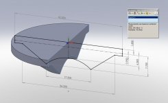
I was given some dimensions for a B&C SW115 so I used that to model a cross sectional area. I used a 422mm cutout in a 18mm baffle.
I can slice the model at different points and measure the cross section.
I found that 2cm wide slices were adequate.
This is a screengrab of the cone and baffle volume at the speaker mid point.
The Tour of Britain Cycle Race comes to our town tomorrow, and a I have a gig in town so I have been busy rebuilding and configuring my PA rig.
I was given some dimensions for a B&C SW115 so I used that to model a cross sectional area. I used a 422mm cutout in a 18mm baffle.
I can slice the model at different points and measure the cross section.
I found that 2cm wide slices were adequate.
This is a screengrab of the cone and baffle volume at the speaker mid point.
Attachments
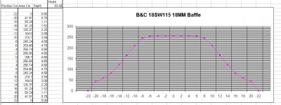
I sliced the model in 2cm increments and put the results into a spreadsheet.
The area is then divided by the internal width of the TH18 cab and an equivalent depth dimension calculated.
The amazing thing is how constant the midddle section of the cone area is.
The area is then divided by the internal width of the TH18 cab and an equivalent depth dimension calculated.
The amazing thing is how constant the midddle section of the cone area is.
Attachments
Hi Xoc1,
Could you give me those dementions or a drawing,I do not know yet how to arrive at them myself ,to determine the plug,I have some others suggestions,but wouldd like yours too!
I lived in Greenville,Sc we had bike rallies every weekend as long as it wasn't raining,Roped off most of downtown,was lots of people ,brewed beer and fun!
I smell like sweat and saw dust,lol. BUT it a good day in Texas,nice and cool,we got rain last night!
Thanks,
NS
Last edited:
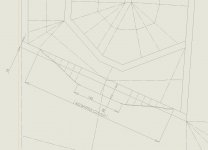
I then used the calculated area dimensions to plot out a cone compensation plotting line to be used in the horn model.
The compensation line starts at the intersection of the internal baffle face and the baffle cut out.
This imaginary line is then used as one side of the throat cross section.
The other side of the horn is shaped to follow this contour and the desired horn throat areas.
I averaged the compensation line and reduced it to 3 sections. This is to make it practical to build in timber.
This process leads me to a throat shape roughly as attached. Which is as far as I have got. I now need a spare day to fettle the rest of the folding, and to concider what else needs to be done.
It is obvious how the cone compensation bend can be used to increase the internal path length of the TH18 -SS15 fold..
Yes it needs more work and a few more sketch lines, but I see it as a valid way of calculating a TH horn throat in a way that can be understood and applied by the DIY builder
Regards
Martin (Xoc1)
The compensation line starts at the intersection of the internal baffle face and the baffle cut out.
This imaginary line is then used as one side of the throat cross section.
The other side of the horn is shaped to follow this contour and the desired horn throat areas.
I averaged the compensation line and reduced it to 3 sections. This is to make it practical to build in timber.
This process leads me to a throat shape roughly as attached. Which is as far as I have got. I now need a spare day to fettle the rest of the folding, and to concider what else needs to be done.
It is obvious how the cone compensation bend can be used to increase the internal path length of the TH18 -SS15 fold.
. Yes it needs more work and a few more sketch lines, but I see it as a valid way of calculating a TH horn throat in a way that can be understood and applied by the DIY builder
Regards
Martin (Xoc1)
Attachments
Hi Martin,
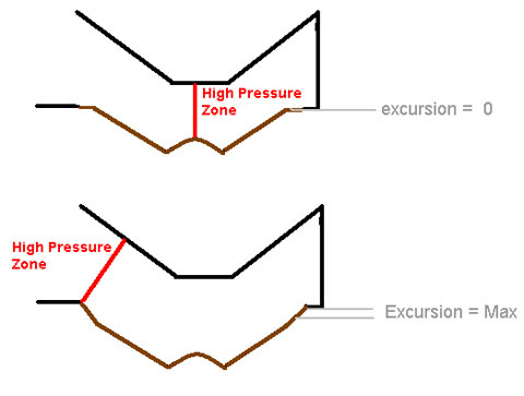
Nice to see you are back in bizz, hope you are doing well. I only want to point out that when the cone moves into the direction towards the mouth, the cone volume increases further. That means the pressure point still ‘travels’ during excursion. If you make the “V” more sharp and closer to the driver-baffle, you can prevent this ‘travel’. Using Xmax or Xvar depends on the type of driver. Xmax for 'less strong' drivers (Low BL, high Vas) and Xvar for 'strong' drivers (High Bl, low Vas).
Nice to see you are back in bizz, hope you are doing well. I only want to point out that when the cone moves into the direction towards the mouth, the cone volume increases further. That means the pressure point still ‘travels’ during excursion. If you make the “V” more sharp and closer to the driver-baffle, you can prevent this ‘travel’. Using Xmax or Xvar depends on the type of driver. Xmax for 'less strong' drivers (Low BL, high Vas) and Xvar for 'strong' drivers (High Bl, low Vas).
Hi Nosmoking I'm not trying to ignore you! Just busy cross posting to get the process I am trying to develop on to the forum.
As you can see from the posts I just put up, the compensation profile is there - you could use some of the simple techniques of horn design to come up with a throat shape - this can be as basic as using cut up bits of paper to get a horn contour to follow an profile.
The large S1 area before the S2 point at the centre of the driver seems to give a bit more lower end - reducing S1 extends the top end extension in a Hornresp sim, but not many have found a practical use for an extended top end response.
DJims Stub Looks OK to me and if its is what Crescendo built then it must work! But the compression at S2 looks quite high with DJims stub. It might not be suitable for everyone - it could depend on a decently robust speaker driver.
Must get to bed - Big Day tomorrow - Should be fun 'Making some Good Noise'
Which after all is the point of all of this effort!
Regards
Martin
Hi Martin,
Wasn't in a big Hurry, Didn't feel ignored,Thanks for your Ideas and Drawing from you and Djim,
I am going to contour the speaker cone to as close as your cross section and Djims drawing,and finish this cabinet,Thanks for EVERYONE'S Help!
Glad your back to health!
NS
Wasn't in a big Hurry, Didn't feel ignored,Thanks for your Ideas and Drawing from you and Djim,
I am going to contour the speaker cone to as close as your cross section and Djims drawing,and finish this cabinet,Thanks for EVERYONE'S Help!
Glad your back to health!
NS
Hi Djim
You can squeeze down S2 to suit whatever driver you desire to use........
I am trying to make this a process that we can understand, and apply, with the tools at our disposal - Surely the at rest position is the average volume as the cone moves up and down.
Cheers
Martin
You can squeeze down S2 to suit whatever driver you desire to use........
I am trying to make this a process that we can understand, and apply, with the tools at our disposal - Surely the at rest position is the average volume as the cone moves up and down.
Cheers
Martin
Hi Martin,
I will try to explain. The cone correction makes it function like the sim, which increase the output at the lowest part of the bandpass.
What makes the driver loosing control over the excursion is the 'travelling' of the high pressure zone as result of the excursion (= changing cone volume) in relation to a 'not moving' cab. To keep the control over the excursion, the "Stub" (or "V" in your case) needs to have the highest compression factor, even when the cone moves away from the stub.
Last edited:
Here's an idea I had while looking at how to do cone correction without having to buy more materials...
What if we took the driver cutout and cut smaller coaxial circles out of it at a 45 degree angle with a saber saw or something then stacking them. It seems that one could pretty closely approximate a cone with that method. Then just attach it onto Internal 2. It may not be totally ideal but would it at least be better than nothing?
For a visualization of what I mean think of making onion volcanos by taking it apart and inverting it.
An externally hosted image should be here but it was not working when we last tested it.
hi kctess5,
If you took a couple of pieces of that clinkie plastic like suran wrap and put it across the cone and then filled the cone with foam you will have to only figure how far away to mount that perfect replica to optimize the cone,Nice pic,I like steak and chicken hibachi,lol.Plum wine is good with that meal Too!
NS
Follow up for post#917
In order to compensate for the changing cone volume as result of excursion (towards S4) you increase the compression factor at S2 by lowering the "stub" or "V".
In order to compensate for the increasing 'overall' compression when the cone moves into the other direction, you need to decrease the compression by making the base of the "stub" or "V" smaller.
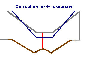
(see my ealier post on 'ideal' models)
In order to compensate for the changing cone volume as result of excursion (towards S4) you increase the compression factor at S2 by lowering the "stub" or "V".
In order to compensate for the increasing 'overall' compression when the cone moves into the other direction, you need to decrease the compression by making the base of the "stub" or "V" smaller.
(see my ealier post on 'ideal' models)
Last edited:
- Home
- Loudspeakers
- Subwoofers
- TH-18 Flat to 35hz! (Xoc1's design)