hi all,
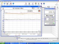
Is this a better responce ?
Thanks,
NS")
I dunno it looks funky with the squiggle in there, can you e-mail the REW file?
The sweep is a sweep and if you are using a multimeter to measure the sweep you are subject to it's averaging accuracy, thus using a sweep to set a level is not recommended due to the variable nature of the signal/meter combination. If you are not measuring at a large level of power these sweeps should not cause the amp output to sag. At high output levels you could monitor the DC supply rails in the amp to see if they sag much. But generally speaking if the amp 2kw+ amp is sagging at 100w or something like that just find a dumpster for it and get a real amp.I noticed voltage fluctuation (+/- 0.5v) during two different frequency sweeps I have. Is this normal? Has anyone measured voltage at the amplifier during an REW or Smaart freq sweep? Does voltage fluctuate (+/- 0.5v)?
Measurement sweep setup suggestion:
- Attach multimeter to amp terminals or wire ends, speaker is not attached at this point.
- Use the REW generator to play a 60Hz sine wave and set amp output voltage, 4Ω: 2v/1m, 10v/5m, 20v/10m. Note the REW generator output level setting, and do not go higher than -12 to avoid digital clipping. Ensure there is no clipping elsewhere in the signal chain.
- Start measurement sweep dialog, set output level to the same value previously used in the generator, set frequency of sweep to 20-300Hz and select the shortest/128k sweep length and set the number of sweeps to 2.
- Click the start measuring button, if you have too much or too little input signal make corrections at the mic/input level side only.
- Look at impulse response and adjust IR windows to 25ms left and 150ms right, then click Apply Windows
- Now look at FR and phase.
Note:
If you use a C-weight SPL meter to calibrate your setup with the 60Hz sine wave the actual level is ~.9dB higher than indicated due to the roll off of the C-weight filter.
If one is to be able to make valid comparisons to other anechoic measurements it is important to measure outdoors well away from large reflective surfaces and use appropriate time windowing on the measurements to produce an accurate response.
hi all,
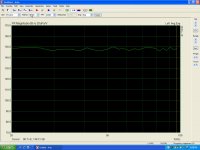
Is this a better responce ?
Thanks,
NS
Hi NS,I dunno it looks funky with the squiggle in there, can you e-mail the REW file?
I was not paying attention, I see the input level is low @ -75dB. Your mike missing it's phantom power?
The source of the squiggle is something late in the impulse response and a little noise possibly.
Attachments
The sweep is a sweep and if you are using a multimeter to measure the sweep you are subject to it's averaging accuracy, thus using a sweep to set a level is not recommended due to the variable nature of the signal/meter combination. If you are not measuring at a large level of power these sweeps should not cause the amp output to sag. At high output levels you could monitor the DC supply rails in the amp to see if they sag much. But generally speaking if the amp 2kw+ amp is sagging at 100w or something like that just find a dumpster for it and get a real amp.
Was using a multimeter to measure very low voltage (>2v). I was under the assumption the sweep swept thru frequencies at the same level - that's what raised this question. I wasn't using the frequency sweep to set level.
Measurement sweep setup suggestion:
- Attach multimeter to amp terminals or wire ends, speaker is not attached at this point.
- Use the REW generator to play a 60Hz sine wave and set amp output voltage, 4Ω: 2v/1m, 10v/5m, 20v/10m. Note the REW generator output level setting, and do not go higher than -12 to avoid digital clipping. Ensure there is no clipping elsewhere in the signal chain.
- Start measurement sweep dialog, set output level to the same value previously used in the generator, set frequency of sweep to 20-300Hz and select the shortest/128k sweep length and set the number of sweeps to 2.
- Click the start measuring button, if you have too much or too little input signal make corrections at the mic/input level side only.
- Look at impulse response and adjust IR windows to 25ms left and 150ms right, then click Apply Windows
- Now look at FR and phase.
Note:
If you use a C-weight SPL meter to calibrate your setup with the 60Hz sine wave the actual level is ~.9dB higher than indicated due to the roll off of the C-weight filter.
If one is to be able to make valid comparisons to other anechoic measurements it is important to measure outdoors well away from large reflective surfaces and use appropriate time windowing on the measurements to produce an accurate response.
Thanks for the notes. Sorry for the short/quick reply. More later
Was using a multimeter to measure very low voltage (>2v). I was under the assumption the sweep swept thru frequencies at the same level - that's what raised this question. I wasn't using the frequency sweep to set level.
Gernerally I think unless you have a "high end" HP or Agilent meter and a perfectly flat output on your sound card you should expect the meter to waver on a sweep.
If you look at the loopback calibration for your setup you can see how much correction was applied to flatten the response. Obviously this is a correction of the cumulative deviation of both the input and output, but the early rolloff of a sound card would be a good reason to see the meter waver during a sweep, but not at a fixed frequency.
Don't sweat the meter, the calfile covers anything in the the loop at the time it's made... Leaving the mic, amp, speaker, and envrionment. You can cal with the amp in the loop if you take care with the voltage, but the amps noise floor may intrude. Probably better to just check the amps FR with your setup, remember to turn off the HPF
You might want to lookup the curve for your mic though 
Let me know if you need a stack of disks; just pay for the shipping 
Hi Oliver,
Interesting ,so do you think in the case of using a 18 " speaker that the disks would react differently as apposed to the stub that goes across the whole camber or if the stub was shorter what difference in responce would that have,
To all of you guys Nice work on cone corrections ,I am beginning to figure it out ,Got REW setup and working just got to get the hows and whys to correctly figured, to hopefully have a correct response curve,!
Have A GREAT Day!
ns
I'm really curious as to where fudging S2 via an inflated cone correction became a good idea? The 18SW115 is really not going to make it to 60mm p-p without dammage, in fact it is hard to drive to 40mm p-p, and that's with HUGE amounts of power.
Hi Dan
S2 compression ratio is currently about 3:1 but this includes the cone correction volume. I'm still unsure about if to stick with this value or reduce the compression ratio. If I can I might reset the geometry for a bigger S2 value but leave enough space for users to be able to fit a double packing piece if needed, to reduce S2 for those users who have the most robust drivers.
What would you think is an optimum S2 compression ratio for budget and top end drivers?
.
Please note that nothing is completely set yet and I am still tweaking the design. I felt that it was time to post the work in progress and get some collaborative input.
Regards
Martin
Hi Martin,
IIRC I went from ~2.4 to 3:1 and it was very noticeable with the 18SW115, but I didn't have the large S1. The increase in compression brought flatter LF response but the sound was compressed in nature, I immediately recognized the difference at any output level. This is really critical to the sound quality in the octave above the box FB. I'm sure your new large S1 will reduce the effect to some extent as will the more open taper you are looking at now.
The problem with the drivers we are using is that they are at the very top of what's available WRT the available force per area. When someone else comes along and puts in an average driver in the box the effect of the compression becomes even more pronounced and it becomes a source of heat induced failure caused by the stalling of the driver motor near FB.
Adding to the list...
Code:
15SW115-8   202.43
15NW100-8   179.8
PD1850-8    160.49
15TBW100-8  153.8
21SW152-8   150.89
15TBX100-8  149.12
18SW115-8   146.00
15SW100-8   141.94
PD2150-8    131.56
18NW100-8   127.05
18PZB100-8  112.48
PA380-8     112.10
18TBW100-8  108.68
2269H       107.35
18SW100-8   106.22
18TBX100-8  105.37
21SW115-8   100.07
4018LF       99.13
2242H        96.38
2226H        83.78
PD2450-8     83.47
PA460-8      80.93
4015LF       76.96
IMPERO 15a   79.26
2268H        68.73
2241H        59.95
2245H        58.49
IMPERO 18a   56.97
Looking at the PD1850 datasheet reveals that the claimed 11.05mm X max is possibly X var as the coil is 28mm long and the gap is 12mm, leaving the real X max at 8mm. The displacement limit is listed as 34mm p-p, that would leave the coil still 3mm in the gap with 25mm hanging below/above. Is the slice of magnet only 25mm thick? They must be make a killing on recone kits
Hi Martin,
IIRC I went from ~2.4 to 3:1 and it was very noticeable with the 18SW115, but I didn't have the large S1. The increase in compression brought flatter LF response but the sound was compressed in nature, I immediately recognized the difference at any output level. This is really critical to the sound quality in the octave above the box FB. I'm sure your new large S1 will reduce the effect to some extent as will the more open taper you are looking at now.
The problem with the drivers we are using is that they are at the very top of what's available WRT the available force per area. When someone else comes along and puts in an average driver in the box the effect of the compression becomes even more pronounced and it becomes a source of heat induced failure caused by the stalling of the driver motor near FB.
Adding to the list...
Code:15SW115-8 202.43 15NW100-8 179.8 PD1850-8 160.49 15TBW100-8 153.8 21SW152-8 150.89 15TBX100-8 149.12 18SW115-8 146.00 15SW100-8 141.94 PD2150-8 131.56 18NW100-8 127.05 18PZB100-8 112.48 PA380-8 112.10 18TBW100-8 108.68 2269H 107.35 18SW100-8 106.22 18TBX100-8 105.37 21SW115-8 100.07 4018LF 99.13 2242H 96.38 2226H 83.78 PD2450-8 83.47 PA460-8 80.93 4015LF 76.96 IMPERO 15a 79.26 2268H 68.73 2241H 59.95 2245H 58.49 IMPERO 18a 56.97
Looking at the PD1850 datasheet reveals that the claimed 11.05mm X max is possibly X var as the coil is 28mm long and the gap is 12mm, leaving the real X max at 8mm. The displacement limit is listed as 34mm p-p, that would leave the coil still 3mm in the gap with 25mm hanging below/above. Is the slice of magnet only 25mm thick? They must be make a killing on recone kits
Hi NEO Dan
Xmax = [(winding depth - magnetic gap depth) / 2] + (magnetic gap depth / 3)
Xmax for PD1850 = ((28mm - 12mm)/2) + (12mm/3) = 8mm + 4mm = 12mm
Hi NEO Dan
Xmax = [(winding depth - magnetic gap depth) / 2] + (magnetic gap depth / 3)
Xmax for PD1850 = ((28mm - 12mm)/2) + (12mm/3) = 8mm + 4mm = 12mm
Hi ZikovF,
I get it, I was just pointing out the relative lack of excursion capability.
A couple posts back 60mm p-p was an expected level of excursion performance
Hi Martin,
IIRC I went from ~2.4 to 3:1 and it was very noticeable with the 18SW115, but I didn't have the large S1. The increase in compression brought flatter LF response but the sound was compressed in nature, I immediately recognized the difference at any output level. This is really critical to the sound quality in the octave above the box FB. I'm sure your new large S1 will reduce the effect to some extent as will the more open taper you are looking at now.
The problem with the drivers we are using is that they are at the very top of what's available WRT the available force per area. When someone else comes along and puts in an average driver in the box the effect of the compression becomes even more pronounced and it becomes a source of heat induced failure caused by the stalling of the driver motor near FB.
Adding to the list...
Code:15SW115-8 202.43 15NW100-8 179.8 PD1850-8 160.49 15TBW100-8 153.8 21SW152-8 150.89 15TBX100-8 149.12 18SW115-8 146.00 15SW100-8 141.94 PD2150-8 131.56 18NW100-8 127.05 18PZB100-8 112.48 PA380-8 112.10 18TBW100-8 108.68 2269H 107.35 18SW100-8 106.22 18TBX100-8 105.37 21SW115-8 100.07 4018LF 99.13 2242H 96.38 2226H 83.78 PD2450-8 83.47 PA460-8 80.93 4015LF 76.96 IMPERO 15a 79.26 2268H 68.73 2241H 59.95 2245H 58.49 IMPERO 18a 56.97
Looking at the PD1850 datasheet reveals that the claimed 11.05mm X max is possibly X var as the coil is 28mm long and the gap is 12mm, leaving the real X max at 8mm. The displacement limit is listed as 34mm p-p, that would leave the coil still 3mm in the gap with 25mm hanging below/above. Is the slice of magnet only 25mm thick? They must be make a killing on recone kits
Hi Dan and others,
Excuse my ignorance - what is the significance of these "code" numbers? The driver I'm using (18SW100) seems to be quite a ways down the list. I went with this driver not only because of neo/lightweight, but also because of all the other great attributes I thought it had (12.5mm xmax, 57mm xmech, etc.) which led me to think I would get less distortion. BUT, the magnets do seem to get quite warm - keep in mind this is after 5 hrs of bass-heavy program material w/peak-stop limiter engaged on the DR260 - so, the signal can be driven hard into the limiter if the dj is hard in the red on the mixer. Which leads me to my next question: what are acceptable temps at the magnet and at what temp do I need to worry (I can buy an IR thermometer to get some numbers). And should I consider another driver? Or do I need to adjust the compression ratio in my (future) cabs? I have 2 and will be building 2 more fairly soon.
Hi Justin,
The numbers are the drivers raw motor force product nominalized for impedance and cone area: N/A per .1M². BL²/Re/Sd
I don't think it's coincidental that the 15" TBX and the 18" SW115 are used in very similar boxes...
Art just posted this, I think he read your post here before he posted in the wrong thread by accident...
As long as you aren't tearing the speaker apart by exceeding Xmech, long term average power is what burns speakers up.
Average power can be very different for different types of music, heavily compressed sine wave like material can have 5-10 times the average LF power compared to say 1980's Steely Dan or the like. HT is generally about sound effects, which usually are fairly short, though there certainly are exceptions.
If you run double the RMS power and have limiters set for no clipping, there is still a very real potential of burning the voice coil if the amp is driven in to hard limiting, as is typical of a DJ mashing in to the red for long periods of EDM.
That said, most amps are capable of + 3 dB output when driven in to hard clipping, in the above scenario one can still burn a voice coil with a clipped amp rated at the speaker's RMS rating.
By the way, most speakers are rated using the AES standard, which uses compressed pink noise with a 6 dB crest factor (normal pink noise is around 12 dB crest factor, still less crest factor than "normal" music), which has only half the average power of a sine wave, which has a 3 dB crest factor.
Although I have tested (almost) all my woofers with sine waves at the AES rated wattage, it has been short term with resting periods between tests, so the average still is around the AES power rating or less. Some of the tests I have done not leaving enough time between tone bursts have resulted in burnt voice coils, and the amp was not clipping at all.
So the short answer about how much power is safe is "it depends".
Art Welter
Dan,Hi Justin,
The numbers are the drivers raw motor force product nominalized for impedance and cone area: N/A per .1M². BL²/Re/Sd
I don't think it's coincidental that the 15" TBX and the 18" SW115 are used in very similar boxes...
Art just posted this, I think he read your post here before he posted in the wrong thread by accident...
For what it's worth, until recently I thought "watts RMS" and the AES 426 rating were the same. After realizing the AES 426 rating using 6 dB crest factor has only half the power of sine waves, I realized how much abuse I have given my speakers in distortion tests.
My 18SW115-4 barely was warm when I was testing with sine waves of 77.5 volts, 77.46V =1500 (real) watts at 4 ohm.
As far as Crescendo's 18SW100 magnet structure getting hot, I'd say it is pretty close to PE
.Art
Hi Justin,do I need to worry (I can buy an IR thermometer to get some numbers). And should I consider another driver? Or do I need to adjust the compression ratio in my (future) cabs? I have 2 and will be building 2 more fairly soon.
In my view the list as presented has limited value. The calculation method, BL²/Re/Sd, doesn’t take account what is left of the driver’s motor force at Xmax and also doesn’t take in account the resistance of the driver as result of the moving mass and the resistance of the suspension.
For instance, traditional Voice Coils usually have 50 to 70% left of their BL product at Xmax. Split-wire Voice Coils still can have >70% of their original BL product. Your 18SW100 has a split-wire VC and can’t therefore be compared with the traditional VC’s. In other words, old school driver such like the PD1850 are rated too high in the list compared to your 18SW100. Therefore Dan’s comment about the PD1850 "they must be make a killing on recone kits" was correct if the BL product was kept high at Xmax.
Another example, the suspension creates more resistance at maximum excursion and is therefore a dynamic figure. However, drivers with a relative high Xlim compared to their Xmax give a less increase in suspension resistance compared with drivers with a low Xlim. So in case you have two identical drivers with the same Xmax and BL force but with a different Xlim, the driver with the highest Xlim should have the lowest suspension resistance at Xmax.
Hi All
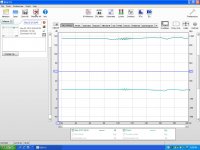
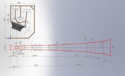
Re hash of TH18 mk1 layout (TH18 mk1_2)
Compression reduced to approx 2.5 :1 . Remembering this includes the cone correction volume so still fairly radical for a DIY TH!
This has increased the dip at 110 hz slightly, but not too much impact on the overall response in Akabak - Yes that is 104 dB@ 82 hz at 1 watt into 8R, in theory at least.
As usual please scrutinise closely for any errrors!
Regards
Martin
Attachments

@Djim
The sound quality issue I am getting at here is not large signal or Xmax dependent, and I do agree that all of the additional losses mentioned degrade performance at large excursion.
Good thing the coil has to go through the center of the gap several times a second or I would be totally talking out of my a$$.
Ah but in this instance the 18SW100 and 18SW115 can be directly compared and the same is true for a conventional motor using the 15" TBX as a reference.
The comment about the PD1850 was a troll in hopes that someone with experience and a ruler could give us the scoop...
A driver that exhibits high BL at Xlim will inductively heat the motor structure until it effectively cooks the coil. I actually have a driver that is improperly engineered in that the suspension locks up while the coil is fully in the gap, and I cooked the coil without burning it.
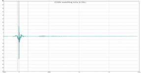
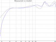
I would not sweat the dip, I think it'll work out just fine in real life:
The sound quality issue I am getting at here is not large signal or Xmax dependent, and I do agree that all of the additional losses mentioned degrade performance at large excursion.
Good thing the coil has to go through the center of the gap several times a second or I would be totally talking out of my a$$.
Ah but in this instance the 18SW100 and 18SW115 can be directly compared and the same is true for a conventional motor using the 15" TBX as a reference.
The comment about the PD1850 was a troll in hopes that someone with experience and a ruler could give us the scoop...
A driver that exhibits high BL at Xlim will inductively heat the motor structure until it effectively cooks the coil. I actually have a driver that is improperly engineered in that the suspension locks up while the coil is fully in the gap, and I cooked the coil without burning it.
Hi All
Re hash of TH18 mk1 layout (TH18 mk1_2)
Compression reduced to approx 2.5 :1 . Remembering this includes the cone correction volume so still fairly radical for a DIY TH!
This has increased the dip at 110 hz slightly, but not too much impact on the overall response in Akabak - Yes that is 104 dB@ 82 hz at 1 watt into 8R, in theory at least.
As usual please scrutinise closely for any errrors!
Regards
Martin
I would not sweat the dip, I think it'll work out just fine in real life:
Attachments
Hi Neo Dan,
The problem is not the high or low compression ratio's in my view but the confusion between the two from the beginning.
If sound quality and SPL are the main goals, in my view, one needs to use drivers that could be called more or less 'ideal TH drivers'. Examples of such drivers are the SW series of B&C or 9000 series of 18Sound, for instance. These 'ideal' drivers would benefit from lower compression ratios in order minimise the negative side effects of compression (of which thermal compression is one of them) while still being able to deliver high excursion/high SPL.
The other 'less ideal drivers', in my view, could benefit from higher compression ratios, in order to deliver high SPL’s within a safe excursion range. I do agree that it will be at costs of sound quality but you can’t have it all. Less than 'ideal' TH drivers will be at costs of sound quality or SPL. That was and still is not different for conventional PA-basshorns. You can see it in the new designs for advanced drivers with the commercial brands. These advanced drivers are also not qualified to be 'ideal' drivers for existing (conventional) basshorn either.
Therefore I suggested earlier two different designs, so all types of PA drivers can be used in a balanced Xoc1-TH18 with maximum performance for PA. It would also help to keep the differences separated and probably prevent further misunderstandings.
Last edited:
- Home
- Loudspeakers
- Subwoofers
- TH-18 Flat to 35hz! (Xoc1's design)