Hi Xco1!
If a magazine like Voice Coil April 2010, pages 19 till 21, Mr John Croft puts his thoughts about born of tapped horn clearly, imagine we can judge it ourselves also, can we?
http://img6.uploadhouse.com/fileuploads/16098/160988160d5bbf0ebc4372633254887d7bf885aa.png
http://img2.uploadhouse.com/fileuploads/16098/160988555332b9136b216fa3c5a44abc73b7e818.png
see patent 2,765,864:
Patent Fetcher - Patent Fetcher PDF Processing
Regards,
Djim,In my (many) attempts to improve the notorious Jbell SS15 I first mentioned it, more than a year ago, with a drawing concept that includes very similar folding style. Since than I have mentioned it in several posts and Art was the only one asking me specific questions about it, half a year ago.
IF* any ethical line is passed, it is not the inclusion of Cone Volume Correction or folding techniques that are both the result of physics and old horn techniques but it is designing tapped horns in the first place.
The "V" load is not just about "Cone Volume Correction", the stub formed on the horn throat side is important, as is the strength of the "V" shape.
Although Tom Danley privately shared the TH-115 plan design using the "V" load with me, it was already quite visible to all in pictures of the DSL TH-812.
This is one of the areas that Hornresp probably underestimates significance of a seemingly minor volume change in location.
That said, I was unaware of the potential of the “V” load when I undertook the design of the Keystone sub, and came up with another idea that seems to work quite well, as evidenced by low distortion, good frequency response, and little power compression at levels well above the AES rating of the BC18SW115-4 used in the design.
Like Thomas Edison experienced, there were many failures in the Keystone prototype process before determining what works well, good design is 10% inspiration, and 90% perspiration.
I wish I’d read the many patents from the 1950s describing in detail what we now identify as “Tapped Horns” when I had started building speaker cabinets back in the 1970s.
When I think of all the 400 pound quad loaded bass cabinets we lugged around for decades that could be replaced by a 150 pound sub using a single driver, makes me appreciate the wealth of information now at our fingertips if we only bother to use it.
Art Welter
were 70s era drivers up to the task to be tap loaded? i keep reading that mxax/xmech advancements facilitated the possibilities.
There are a number of drivers from the 70s and before that work fine in the right TH.were 70s era drivers up to the task to be tap loaded? i keep reading that mxax/xmech advancements facilitated the possibilities.
There are drivers that can put out far more level now due to increased Xmax.
Xmax determines SPL output in any type of enclosure.
A TH can allow about 6 dB more output from the same speaker at the same excursion over a BR, assuming the cone is stiff enough to take the additional stress of horn loading. Many drivers that sim well in a TH ultimately can't put out much more output in a TH compared to BR because of cone deformation at high throat pressure.
Obviously, a 3mm Xmax speaker will have far less output potential than an 18mm Xmax speaker, but a 6 dB gain is a big deal no matter what the available Xmax is.
That said, in the days of 3mm Xmax (or less) woofers, the available amp power was a small fraction of what is available cheaply today, the potential to push the speakers beyond their limits was far less.
Art
Actually now that I think about it your suggestion of a ring would make the most sense as it will displace the least volume and allow for the longer path length. I would make it a optional add in for the test cabinet.
Sounds like you are thinking of implementing just one ring (with or without the V-shape?). Where are you thinking of putting the one ring?
Hi Art,The "V" load is not just about "Cone Volume Correction",
Did I make such claim?
Cone correction cannot be used above an S-shaped throat and the V correction makes the difference between the sides even worse... Just a small reminder, other drivers in the Danley TH18 didn't seem to have a long life time
(Edit: we tested V-shape cone corrections only in the symmetric folding lay-outs that don't have a S2 issue...)
I think he might just be referring to these (and a couple other) mentions where "V-shape" and "cone correction" were in the same sentence..
Hi!
Correct author's name on post #581 should be James Croft.
Forgot to mention patent nr.3,047,090:
Patent Fetcher - Patent Fetcher PDF Processing
Regards,
Correct author's name on post #581 should be James Croft.
Forgot to mention patent nr.3,047,090:
Patent Fetcher - Patent Fetcher PDF Processing
Regards,
Thanks Justin, I guess I'll have to be more specific next time and use the words 'Danley's V-method' and 'V-shape cone volume correction'I think he might just be referring to these (and a couple other) mentions where "V-shape" and "cone correction" were in the same sentence..
Last edited:
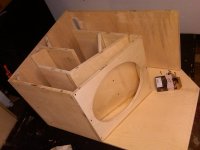
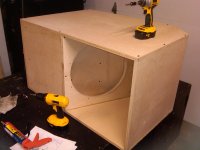
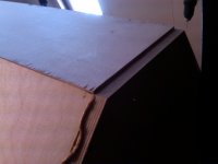
Makin progress. Just bein held up by this small lip on the caster board. I'll either have to wait til I get to a table saw again to rip the board a little better or get a few squares of 80 grit for my palm sander Gonna go check if I can manage with my circular saw in a bit.
Gonna go check if I can manage with my circular saw in a bit.Attachments
Sounds like you are thinking of implementing just one ring (with or without the V-shape?). Where are you thinking of putting the one ring?
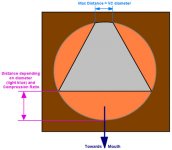
This is the general idea:
Attachments

Hi NEO Dan,
Post #591: "...general idea..."
The "V-shape w/ the flat" in blue already takes care of the cone correction. Also, this method only applies if there is no throat chamber with reduced (e.g.: same as S2) throat to horn coupling port (Ap1/Lpt in Hornresp).
Regards,
Post #591: "...general idea..."
The "V-shape w/ the flat" in blue already takes care of the cone correction. Also, this method only applies if there is no throat chamber with reduced (e.g.: same as S2) throat to horn coupling port (Ap1/Lpt in Hornresp).
Regards,
Last edited:
Hi Dan,
It’s difficult to predict exactly what is going to happen but one thing for sure, you are adding a relative high compression factor (this is what you want to prevent as much as possible). I can't see it will correct the S2 position either, sorry.
Since there seems to be some sort of confusion about the different elements needed, I’ll sum them up:
A) Cone Volume Correction for correcting the extra volume the cone is creating in the first section of the horn/pipe. This correction needs to be placed carefully and can’t be simplified to just a flat surface. There is a relation between correction/distance/cone. It also doesn't need to be perfect (shape-wise) since it is used for subs with relative long wavelength.
B) Wavelength Correction between the two edges of the driver. Because the driver is mounted at a 90 degree angle into the horn/pipe, one edge of the driver sits more close towards the mouth than the other. The distance differences between the two edges is causing phase shifting problems and maybe it even shifts the lowest resonance upwards a little. If people want to know about it search for phase plug as used in mid-horns for instance. It has a similar function.
Both elements are used by Danley, who is also an authority in old school horns for those who didn’t know. The reason I mention this is because both correction are used by old school designers. In other words you can search for those sources yourself.
The difficulty is to integrate them both at the same time. In a symmetric fold system with centre position of the driver it easy to do, but for the 'classic' SS15 folding it needs some clever thinking.
My earlier suggestion of using a S-shape opening for the speaker baffle allows this phase shifting correction (and repositioning of the S2) but needs less cone volume correction, and probably on just one half of the driver since it will be covered halfway by the S-baffle.
Last edited:
Wavelength size does matter, phase plugs are needed at mid and high frequencies.Since there seems to be some sort of confusion about the different elements needed, I’ll sum them up:
A) Cone Volume Correction for correcting the extra volume the cone is creating in the first section of the horn/pipe. This correction needs to be placed carefully and can’t be simplified to just a flat surface. There is a relation between correction/distance/cone. It also doesn't need to be perfect (shape-wise) since it is used for subs with relative long wavelength.
B) Wavelength Correction between the two edges of the driver. Because the driver is mounted at a 90 degree angle into the horn/pipe, one edge of the driver sits more close towards the mouth than the other. The distance differences between the two edges is causing phase shifting problems and maybe it even shifts the lowest resonance upwards a little. If people want to know about it search for phase plug as used in mid-horns for instance. It has a similar function.
As Tom Danley has often pointed out, as long as two sources are within about 1/4 wavelength of each other, they will sum coherently.
At 100 Hz, as long as the leading edge and trailing edge of the cone exits are within around 34 inches of each other, (just a bit under a meter) "phase shifting" is a non-issue.
Even as high as 200 Hz, there is no problem whatsoever in this regard with an 18" driver.
At 200 Hz, any "Flat to 35 Hz!" TH will have problems far worse from the combination of the front and rear output, totally swamping the approximate 15" leading edge to trailing edge path length difference of the radiating surface of an 18" driver.
C) The "stub" on the throat side of the "V" used in various Danley TH serves a function other than described in your "A" or "B" summation.
Art
Last edited:
The difficulty is to integrate them both at the same time. In a symmetric fold system with centre position of the driver it easy to do, but for the 'classic' SS15 folding it needs some clever thinking.
My earlier suggestion of using a S-shape opening for the speaker baffle allows this phase shifting correction (and repositioning of the S2) but needs less cone volume correction, and probably on just one half of the driver since it will be covered halfway by the S-baffle.
And it also creates more pressure as well, right?
What about incorporating cone volume correction with your other throat idea? I assume it will need "less cone volume correction" like above. Maybe it'll work a little better with it.
Attachments
I think at some point you need to decide if you want to make something exactly like a model or if you have other priority's like reliability. IMO obscuring the driver cutout with the S or other oddly shaped restrictive cutouts is a sure route to cause problems. I would expect to implement a disc above the cone that would be no more restrictive than S2, and of course the volume correction would also be accounted for.
If he didn't imply those functions and maybe only uses impedance correction, I find it difficult to believe the driver will hold at the power ratings he is claiming.C) The "stub" on the throat side of the "V" used in various Danley TH serves a function other than described in your "A" or "B" summation.
Yes, the S-baffle also introduces a (low) compression ratio.And it also creates more pressure as well, right?
Probably the pyramid-shape baffle makes it too complex to use correction of the cone volume.What about incorporating cone volume correction with your other throat idea? I assume it will need "less cone volume correction" like above. Maybe it'll work a little better with it.
It was an idea to work from and it probably doesn’t even have to go half way to find the right balance. It's just for correcting the position of S2 to the centre with the smallest amount of compression possible.IMO obscuring the driver cutout with the S or other oddly shaped restrictive cutouts is a sure route to cause problems.
I don’t see how you can compensate the volume any longer in a correct way.I would expect to implement a disc above the cone that would be no more restrictive than S2, and of course the volume correction would also be accounted for
Last edited:
Okay, Phase shifting is probably not the correct term but if Danley doesn't use a similar approach how is it possible to expect linear cone movement of both edges of the driver at high excursion when their position is separated by the diameter of the cone? Also both edges seem to have a different distance towards S2 since it looks like S2 it is not centred in the middle of the cone in this fold-type enclosure. Also, both edges have a different position in the horn/pipe and seem to be loaded differently..."phase shifting" is a non-issue.
Last edited:
- Home
- Loudspeakers
- Subwoofers
- TH-18 Flat to 35hz! (Xoc1's design)