Hi Oliver,How do you model this?
I do it two ways and check the differences; one way is to stretch the concept like usual, and the other way is to use "TH1" in the "Input Parameter" page and recalculate the positions, that Neo Dan pointed out to me. The last one looses the capability to put a horn parameter between S2 and S4. It would be better if you use Akabak, but I hope David will increase the number of horn parameters. Besides, there are more important things you can't model.
Hi Oliver,Thanks. Yes, this does call for AkAbak.
Let me put it this way, maybe its not optimised, but it does improve compression figures considerably and gives low freq. extension for the drivers mentioned in my earlier post. It's not tested with the 3015lf (as far as i know) but I think it will be less promising.
Last edited:
oftopic ,how does one run akabak under win7 x64?Hi Djim,
Thanks. Yes, this does call for AkAbak.
Regards,
i tryed compatebilety mode and dos envirement.
Hi epa,
I'm running Xp, and will as long as possible. Sorry, but no further help.
Regards,
tnx oliver
i got it running on a vm.
a got an extra section in ,and a hpf.
now i want to put in a eq,but cant figger out how .
sorry 4 the oftopic
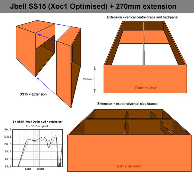
In Post # 31 here - http://www.diyaudio.com/forums/subwoofers/189223-crazy-box-design-input-please-3.html - i posted a screeie of a design i did, which included an extended mouth.
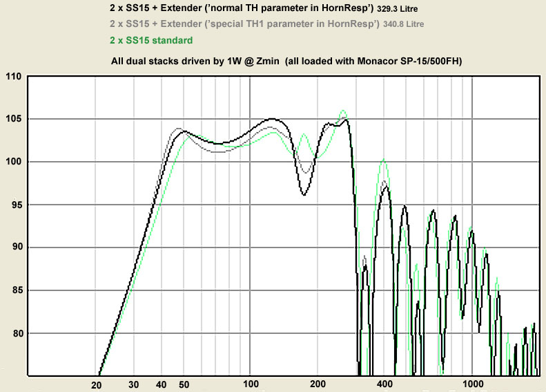
Djim posted an extender in Post # 461 here - http://www.diyaudio.com/forums/subwoofers/190635-th-18-flat-35hz-xoc1s-design-31.html - His graph clearly shows improvements below 55Hz, & also up to 150Hz")
So based on that, i'm wondering how my design would fail to offer some LF improvement/s ?
TIA
Djim posted an extender in Post # 461 here - http://www.diyaudio.com/forums/subwoofers/190635-th-18-flat-35hz-xoc1s-design-31.html - His graph clearly shows improvements below 55Hz, & also up to 150Hz
So based on that, i'm wondering how my design would fail to offer some LF improvement/s ?
Originally Posted by djk In Post # 32 http://www.diyaudio.com/forums/subwoofers/189223-crazy-box-design-input-please-3.html
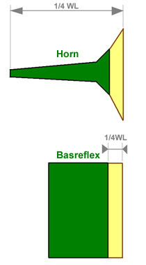
The 'horn' part of the port adds nothing below 100hz, it's just a port.
TIA
Hi Oliver,
The model was only intended to show the difference in principles. In reality the 'big step' isn't a big problem below 120Hz. Its length is much smaller than 1/6 of the hornpath length.
@ Djim
Gotcha Thanks
In other words my example is increasing the length of the hornpath
Gotcha
Thanks Compression Ratio?
I’m Thinking about the horn throat design for the TH18
My first observation is about the compression ratio (as reported in Hornresp when you hover over the S2 area.)
Most people on DIYaudio try to keep this ratio fairly low. 2:1 or thereabouts.
At this point in a TH you are only looking at half the driver, the other half is past that point in the horn. Does this reduce the supposed compression ratio at the S2 area by at least 50%.?????
Your thoughts please!
Regards Martin. (Xoc1)
I do think tapped horns can support higher compression ratio's than front loaded and back loaded horns can.
When sound is seen from the perspective of moving particles (part of the dual theory) as well as behaving as a mass (spring/mass). Air molecules in a front loaded horn, are pushed by one side of the cone. The entire air mass is thus "resting" on one side of the cone and in the example of an outward cone movement are pushed through the throat and simultaniously counteracting/pushing on the cone.
In a tapped horn (and other similar designs the mass/molecules are pushed by one side of the cone whilst the other side pulls them through the throat (vacuum). That could help to easy the stress on one side of the cone, as it's helped from near the mouth.
Best regards Johan
When sound is seen from the perspective of moving particles (part of the dual theory) as well as behaving as a mass (spring/mass). Air molecules in a front loaded horn, are pushed by one side of the cone. The entire air mass is thus "resting" on one side of the cone and in the example of an outward cone movement are pushed through the throat and simultaniously counteracting/pushing on the cone.
In a tapped horn (and other similar designs
the mass/molecules are pushed by one side of the cone whilst the other side pulls them through the throat (vacuum). That could help to easy the stress on one side of the cone, as it's helped from near the mouth.Best regards Johan
Hi Johan, that makes sense but only at low frequencies. Is that not what happens when the driver becomes unloaded below the resonant frequency and a hi-pass filter is needed to avoid excessive excursion.In a tapped horn (and other similar designs
Best regards Johan
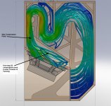
I think that the maximum compression in the TH horn is reached at the point in the horn next to the edge of the driver, not the centre.
As such the Hornresp compression ratio reported is still useful information but does not specifically relate to the actual S2 point in the horn.
Flow analysis sim screenshot attached to illustrate this.
I am trying to concider what is really happening in the TH horn throat.
Regards Martin
Attachments
- Home
- Loudspeakers
- Subwoofers
- TH-18 Flat to 35hz! (Xoc1's design)