Hi Pasc,Hi!
The grill to be attached with screws to SS15 is made so:
For TH18 could put one more screw hole to fix it directly to the slot or slots I was reffering to the sides.
Regards,
Very nice build, did you make your measurements of the Xoc1 with or without such grill fully attached?
Hi Iand,
Oooh, you know all about this. In that case I only like to add that you don’t have to use copolymer with its 'standard' characteristics as bonder. There are new solutions, less hard with better elastic properties. Its origin comes from joint operations within their AEB group and some funny Italian car builders
Cheers,
Djim
I know there are other resins with better damping, but this still doesn't really fix the bell resonance -- a thin cone is stiff for axial stresses but not for the types of cone resonance you described. Adding damping reduces the Q, but if you add enough percentage of the filler to give significant damping you're adding quite a lot of mass and losing quite a lot of stiffness, in which case you might as well go back to inherently damped paper pulp (maybe with some added chopped carbon or glass fibres).
A sandwich diaphragm is really the best way to go -- Leak did it with the Sandwich in the 1960s (ali skins over expanded ali) and KEF with the B139 in the 1970s (ali skins over polystyrene), but there are much better materials available now.
Leak Sandwich Loudspeaker
The reason it hasn't been more widely adopted is that normal cones are seen as "good enough" for most applications so everyone uses them, and they're much cheaper and easier to make. It's only the people who are crazy about sound quality (B&W) or want to get good efficiency and high power levels (TC) and don't care so much about the cost who are using this technology.
Which is a pity, I'm sure if one of the PA driver manufacturers started to use it the price would come down as the volumes go up, and it might then be more widely available.
Combine it with the radial neo motor technology that TC sounds use now (1.5" deep coil in 3" deep gap, 31mm linear Xmax at 3% THD) and put the coil diameter up to 6" (still not too heavy) and you'd have an unbeatable sub driver.
Whether anyone would be willing to pay the price is another matter...
Last edited:
Hi Pasc,
Very nice build, did you make your measurements of the Xoc1 with or without such grill fully attached?
Hi!
Without.
TH18 one need to be builded in future, after finishing it (filling ok, sanding and painting).
Regards,
imho, succes with composite cones in the early years of application of these types of cones where due to the 'imperfection' of quality standards. I'll try to explain this: the glueing of the layers was randomly 'inperfect' but the glued surface as a whole created a well-dampened and still stiff enough cone. Nowadays glueing and assembly of the same kind would be done 'better and less randomly imperfect'. As a result we get something 'better' evenly bonded togheter, but less dampened due to the 'perfectionated' fabrication-methods. Did you never wonder how our own ears are shaped NOT regularly and composed of soft, harder, skinnier and thicker areas. Chaotic but in the same time Gaussian evenly divided. Something like that, is the key to suppress most resonances. BTW most of those bextrene kef woofers received a randomly smear of a kind of silicone-glue all over their surface, a bit concentric but a 'smear' not exactly evenly divided. A whole bunch of succesful woofers have on the backside an irregular surface just to create a chaos of weaker and stiffer spots to enhance random dampening over a wider frequencyband just to target partial and overall resonancies. A good black smith knows how to 'work' a good knife. The 'right mixture' does exist but has many recepies as nature shows us with all those different shapes of ears still tending to appriciate the same 'quality' of music reproduction.
imho, succes with composite cones in the early years of application of these types of cones where due to the 'imperfection' of quality standards. I'll try to explain this: the glueing of the layers was randomly 'inperfect' but the glued surface as a whole created a well-dampened and still stiff enough cone. Nowadays glueing and assembly of the same kind would be done 'better and less randomly imperfect'. As a result we get something 'better' evenly bonded togheter, but less dampened due to the 'perfectionated' fabrication-methods. Did you never wonder how our own ears are shaped NOT regularly and composed of soft, harder, skinnier and thicker areas. Chaotic but in the same time Gaussian evenly divided. Something like that, is the key to suppress most resonances. BTW most of those bextrene kef woofers received a randomly smear of a kind of silicone-glue all over their surface, a bit concentric but a 'smear' not exactly evenly divided. A whole bunch of succesful woofers have on the backside an irregular surface just to create a chaos of weaker and stiffer spots to enhance random dampening over a wider frequencyband just to target partial and overall resonancies. A good black smith knows how to 'work' a good knife. The 'right mixture' does exist but has many recepies as nature shows us with all those different shapes of ears still tending to appriciate the same 'quality' of music reproduction.
One of the reasons B&W use woven Kevlar -- and I assume woven carbon fibre will do the same -- is that it's not radially symmetric, so the speed of sound in the cone is different in different directions (along the fibres vs. at 45 degrees) which also breaks up the resonances.
This does also mean the stiffness could be drastically different, so maybe it would be best to have the front and rear skins set 45 degrees apart...
I think even 30/60 degrees could give better results due to even less symmetricality (less concentric nodes). Eventually one can deform the woven tissue by applying some torsion to it, so inner to outside fabric pattern changes, more dense near the coil, less on outer limits. But that has to the proven by tests in labs with knowledge and resarch-$$$$'s. This solution could resolve also the fragile-neck-problems many of the ultra-high-powered cones have that are discussed in this topic.
I'm not abusing my 'carbon' TAD 1201's but the JBL 2480 phenolics can take anything, just to make a comparison between a fragile beauty and a robust beast
.... Bart Locanthi, why did you leave us, we need you here
Community uses two layers of carbon fiber over a foam core to form the 7" cones used in the M4 transducer (4-1/2" voice-coil).
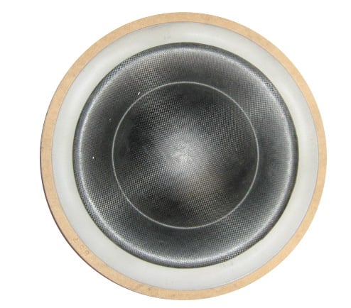
"The M4's diaphragm is a composite structure of carbon fiber
skins over a rigid, thermo-formed foam core. This results in
an extremely stiff yet low mass pistion. This construction is
largely respobsible for the M4's low distortion even at very
high output sound pressure levels."
**********************
Can anyone tell from the photo if the CF is woven or biaxial?
the pdf files on the first page of this thread is the final design?? i wanted to build some of these a while back, but had to spend my driver money else where. i just purchased the plywood to build 4 CBe cabinets, but this cabinet seems to be a little easier to move around.
Hi Scameron78
The plans in post 6 have never been modified.
I have tried a few times to improve on the original but so far have not come up with anything that sims significantly better in Akabak.
As it is, it seems OK for usage around 1KW level, but might need some work for drivers that can handle 2KW plus.
Did you have any particular drivers that you want to use?
However as I have a bit of time on my hands at the moment, I have been working on this again and I seem to have made some inroads.
Back in March 11, I posted this mod of the SS15
http://www.diyaudio.com/forums/subwoofers/170771-single-sheet-th-challenge-74.html#post2510499
I have reworked this a few times since - increasing the timber to 18mm and tweaking, and seem to have come up with some improvement, and kept to one 8' x 4' sheet!
If nothing else this mod utilises the only wasted space in the orignal!
Recently Weltersys posted that that this style of horn throat might have advantages.
http://www.diyaudio.com/forums/subwoofers/204978-danley-th-221-drawings-4.html#post2875252.
So I am having another go at it.
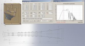
Attached is the reworked SS15. The original SS15 sim is the grey SPL line.
There is increased ripple above 135Hz, but no one so far has been interested in the extended response, so its probably better to concentrate on the efficiency below 100Hz.
If I come up with anything better for the TH18 I will post my findings here, but no promises.
Regards Martin (Xoc1)
The plans in post 6 have never been modified.
I have tried a few times to improve on the original but so far have not come up with anything that sims significantly better in Akabak.
As it is, it seems OK for usage around 1KW level, but might need some work for drivers that can handle 2KW plus.
Did you have any particular drivers that you want to use?
However as I have a bit of time on my hands at the moment, I have been working on this again and I seem to have made some inroads.
Back in March 11, I posted this mod of the SS15
http://www.diyaudio.com/forums/subwoofers/170771-single-sheet-th-challenge-74.html#post2510499
I have reworked this a few times since - increasing the timber to 18mm and tweaking, and seem to have come up with some improvement, and kept to one 8' x 4' sheet!
If nothing else this mod utilises the only wasted space in the orignal!
Recently Weltersys posted that that this style of horn throat might have advantages.
http://www.diyaudio.com/forums/subwoofers/204978-danley-th-221-drawings-4.html#post2875252.
So I am having another go at it.
Attached is the reworked SS15. The original SS15 sim is the grey SPL line.
There is increased ripple above 135Hz, but no one so far has been interested in the extended response, so its probably better to concentrate on the efficiency below 100Hz.
If I come up with anything better for the TH18 I will post my findings here, but no promises.
Regards Martin (Xoc1)
Attachments
Hi Martin (Xoc1),
Entering your data into Hornresp I get slightly different results in the SPL, e.g.: the dip @ 155Hz goes to 99.5 dB, from the SPL response your picture shows (do I need to update?).
When changing S1 in the Wizard it does not look like increasing it beyound where it would naturally fall with the board opposing the driver provides any improvement, to me it looks like about 320cm^2 would be the optimum (give or take 100cm^2); it does smoothen out the passband ripple though.
Regards,
Hi Scameron78
The plans in post 6 have never been modified.
I have tried a few times to improve on the original but so far have not come up with anything that sims significantly better in Akabak.
As it is, it seems OK for usage around 1KW level, but might need some work for drivers that can handle 2KW plus.
Did you have any particular drivers that you want to use?
not sure on drivers just yet. i will have to save again, but leaning towards either the B&C 18tbx100 or the 18sound 18lw2400.
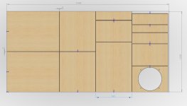
couple things, i went in cad and sketched up the cabinet in metric using the 18mm material. the material i have is 19mm roughly, so i reworked the cabinet very slightly to allow for the extra 1mm. i don't think the extra material thickness will hurt the response of the cabinet. what do you think. i scaled it down for standard dimensions because i am in the United States.
the bracing you proposed about mid way through this thread, are you still satisfied with that proposal? also, lets talk about how to handle the cabinet. natural handles can be routed in on the top/back and casters installed (i believe someone has done this already here). a simple tip back and off we go. now i want to also route in some kind of natural handle on the bottom shelf towards the front. not sure if leaving them open would cause problems to the response in the mouth. i'll try and get a sketch of this today.
Hi Martin,Back in March 11, I posted this mod of the SS15
http://www.diyaudio.com/forums/subwoofers/170771-single-sheet-th-challenge-74.html#post2510499 I have reworked this a few times since - increasing the timber to 18mm and tweaking, and seem to have come up with some improvement, and kept to one 8' x 4' sheet! If nothing else this mod utilises the only wasted space in the orignal!
It's a pity that your optimised SS15 is no longer fully optimised for the latest 3015lf version, but it makes a difference for the RCF L15P200AK and the Monacor SP-15/500FH (same as the Faital Pro 15FH500). The difference is bigger in reality than in the model, especially at high power.
Last edited:
Hi Martin,
It's a pity that your optimised SS15 is no longer fully optimised for the latest 3015lf version, but it makes a difference for the RCF L15P200AK and the Monacor SP-15/500FH (same as the Faital Pro 15FH500). The difference is bigger in reality than in the model, especially at high power.
Hi Djim
Yes I have noticed that this set out works well with different drivers that are more suited to reflex cabinets.
This sims well with my Fane XB 15" driver which did not work well in the Jbell SS15 sim
The 3015LF sim is mostly about comparing apples with apples!
Regards Martin
Hi TB46Hi Martin (Xoc1),
Entering your data into Hornresp I get slightly different results in the SPL, e.g.: the dip @ 155Hz goes to 99.5 dB, from the SPL response your picture shows (do I need to update?).
When changing S1 in the Wizard it does not look like increasing it beyound where it would naturally fall with the board opposing the driver provides any improvement, to me it looks like about 320cm^2 would be the optimum (give or take 100cm^2); it does smoothen out the passband ripple though.
Regards,
Hopefully my physical dimensions in the sim are accurate.
Please try some different drivers, this set out seems to fill in the smile curve
Don't forget that the panels still have to come out of one sheet for it to be a SS15. No material left for bracing, but it is 18mm thick
I have even allowed for a 4mm kerf for the cuts between the panels but some angled cuts are required to get it out of one sheet.
Regards Martin
Attachments
- Home
- Loudspeakers
- Subwoofers
- TH-18 Flat to 35hz! (Xoc1's design)