Well, i am not a whiz in thielle small paramaters but looks like a BL of 25 is a bit low for the TH18
although the resonant freq is 29.9
and the xmax of 12mm seem low also for todays standards
i think is a bit under on what the TH18 needs
But let the TH gurus chime in and give a veredict on this driver

although the resonant freq is 29.9
and the xmax of 12mm seem low also for todays standards
i think is a bit under on what the TH18 needs
But let the TH gurus chime in and give a veredict on this driver
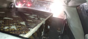
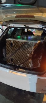
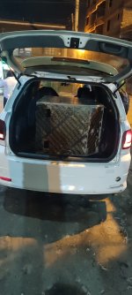
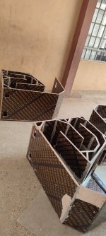
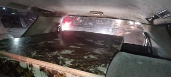
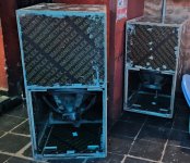
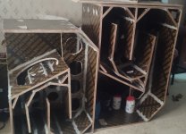
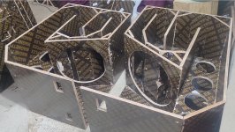
i managed to finished the beast. it is 610mm x 80mm x 1220mm. I made two 21" and 18" . The 21" is huge it fills up the boot on a suv vanin real time real life the 21" driver in the xoc 18inch box😁😁🥰
it uses 4ft x 8ft boards 2 and 1/4 boards . It sounds deeper than the 18 . also it needs more juice
 i.e amplifier power .
there are pictures comparing xoc 21 with the xoc18 . see the difference all
thanks all for this amazing forum . have fun all
 😁😁
😁😁Attachments
-
 IMG_20231015_191547.jpg172.7 KB · Views: 138
 -
 IMG_20231015_193151.jpg228.2 KB · Views: 134
 -
 IMG_20231015_193202.jpg259.6 KB · Views: 141
 -
 IMG_20231025_130810.jpg349.2 KB · Views: 138
 -
gtY xoc121 cutlist 1pieces .pdf711.7 KB · Views: 40
-
 gtY th121 f.jpg41.5 KB · Views: 142
 -
 gtY th121 e.jpg42.4 KB · Views: 139
 -
 gtY th121 c.jpg86.7 KB · Views: 143
 -
 IMG_20231015_191538.jpg210.4 KB · Views: 151
 -
 xoc21 next to xoc18 .jpg476.7 KB · Views: 147
 -
 xoc21 next to xoc18 b.jpg401.8 KB · Views: 161
 -
 xoc21 next to xoc18 d.jpg413.3 KB · Views: 160
Last edited:

The lower Fs means that the low Q´s do not indicate motor strength that much. I.E. the motor is weaker compared to other speaker with the same Q but higher Fs. Anyways, 12mm of Xmax is average in high end, not half bad at all. Also, these drivers certainly can move some more, effortlessly without much hearable issues and distortions. RCF and BMS certainly are good in this department. Not sure, BMS was listing their Xmax for a long time as coil length minus pole piece depth divided by two. That´s not how others list their Xmax. If others would list it that way, they would NOT post better specs as they do now. Keep that in mind.Well, i am not a whiz in thielle small paramaters but looks like a BL of 25 is a bit low for the TH18
although the resonant freq is 29.9
and the xmax of 12mm seem low also for todays standards
i think is a bit under on what the TH18 needs
But let the TH gurus chime in and give a veredict on this driver
View attachment 1217437
The 21" is huge it fills up the boot on a suv van.
Did you play it inside the vehicle?
nope sir , just used the suv for transport. but i have ever tried this th18 https://www.diyaudio.com/community/threads/15-tapped-horn-with-rcf.170749/post-5051872 it had an rcf 18 . but inside a suv a ported dual twelve inch sounded more powerful . i used a 900wts at 4ohms amp
Hi.
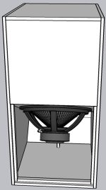
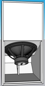
So I'm trying to 3d model the TH 18 with this plan. I have a few issues on the plan, its my first rodeo so I would like to ask from the more experienced builders is there a reason to be concerned or if someone is able to point out where I made the mistake on the measures.
The sketch:

The (possible non-)issues, correct measures in red:

Those wont align with the cut list measures without blowing the whole measurement set up apart.
Is it okay just to go with these?
Im trying to model the box and run some hornresp tests on the A & D drivers.
So I'm trying to 3d model the TH 18 with this plan. I have a few issues on the plan, its my first rodeo so I would like to ask from the more experienced builders is there a reason to be concerned or if someone is able to point out where I made the mistake on the measures.
The sketch:
The (possible non-)issues, correct measures in red:
Those wont align with the cut list measures without blowing the whole measurement set up apart.
Is it okay just to go with these?
Im trying to model the box and run some hornresp tests on the A & D drivers.
Last edited:
Hi.
So I'm trying to 3d model the TH 18 with this plan. I have a few issues on the plan, its my first rodeo so I would like to ask from the more experienced builders is there a reason to be concerned or if someone is able to point out where I made the mistake on the measures.
The sketch:
Hello,
The way you quoting the model might be good for replicating a model but it will not work if you want to scale the model.
Below a link to a website you can download the CAD model for this box and compare with your. You just need to adjust it from 15" to 18". There is a tutorial session where you can find more useful information.
https://freeloudspeakerplan.rf.gd/pages/th-ss1.htm
No need to scale, building it in the 18 inch configuration! Need to check the CAD models after were through with christmas 🤝 Mostly just want to type in A&D 18” driver specs to see if they fit and get a quote from them!Hello,
The way you quoting the model might be good for replicating a model but it will not work if you want to scale the model.
Below a link to a website you can download the CAD model for this box and compare with your. You just need to adjust it from 15" to 18". There is a tutorial session where you can find more useful information.
https://freeloudspeakerplan.rf.gd/pages/th-ss1.htm
I rendered some views today since I got the model ”done”.
Also made the straightened tube with relations. Im missing 7,5mm in the total length, might be just some difference in the path marking. No pic of the corrected straightened tube tho and now Im on my phone.
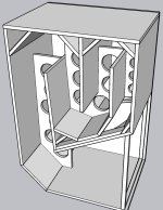
In my POC3 build, I didn't bother adding the panels marked with an "X" in the diagram. Even the one down at the bottom. If you plan to inset a handle into the top of the enclosure for easy transport purposes (put wheels on the bottom corner, tilt the cabinet to move it), then leave that panel in.
Also, there seems to be path miscalculation in the image.

Also, there seems to be path miscalculation in the image.
@Brian Steele what was the frequency response of the box , with or without the reflectors?
what is the frequency response of the cabinet with and without reflectors.Yeah corner reflector do more harm than good plus rob internal volume, on the pics look nicer but audio wise is just a waste of wood.
how do i install this program?Hello,
The way you quoting the model might be good for replicating a model but it will not work if you want to scale the model.
Below a link to a website you can download the CAD model for this box and compare with your. You just need to adjust it from 15" to 18". There is a tutorial session where you can find more useful information.
https://freeloudspeakerplan.rf.gd/pages/th-ss1.htm
Idk for the TH18 but same thing was discussed in the jbell SS15 thread , he show the results with reflectors and without , conclusion....reflectors = waste of resources and time, but do your own research if you don't believe us, just wanted to save you time and cost.what is the frequency response of the cabinet with and without reflectors.
And In some other horn threads this was touched with the same result , the general consensus was to avoid corner reflectors.
But again, if you don't believe, do the myth busters test.
how do i install this program?
As all other programs you have in your computer.
The way you install will depend from the operation you are using, WIndows, Linux, MacOS.
You can check it's website and google for help.
https://www.freecad.org
Allright, thanks. Well go with two corner panels since mobility is very important in this case. I made the model with these instructions. Glad its easy to change. I wonder where the path miscalculation is, since I tried to model the cabin with correct measurements. Might have to look into it.In my POC3 build, I didn't bother adding the panels marked with an "X" in the diagram. Even the one down at the bottom. If you plan to inset a handle into the top of the enclosure for easy transport purposes (put wheels on the bottom corner, tilt the cabinet to move it), then leave that panel in.
Also, there seems to be path miscalculation in the image.
View attachment 1250870
Anyway I think I wont achieve building it with .01 or even .1mm tolerance (of course I'll try) so maybe theres no need to worry about that.
Heres the corrected path measures, it looks okayish to me.
But yeah if it does not matter, well skip the corner panels. How about compensating for the driver concave? Is that still a thing? I could 3d print a piece for that.
Corner reflectors only since they are on the plan I copied, no other reason!Why the corner reflectors?
Check out jbell's SS15 thread where he has measurements with and without corner reflectors.
- Home
- Loudspeakers
- Subwoofers
- TH-18 Flat to 35hz! (Xoc1's design)