Hi USRfobiwan
yes its crazy. the half of the 36 are painted, the rest will follow next week. when ready we want to test the whole set in a townhall for 11.000 pax. the problem is we don't have enough top speakers for testing") . normally two of the guys run a small rental business, the others are just audio enthusiasts.....
. normally two of the guys run a small rental business, the others are just audio enthusiasts.....
yes its crazy. the half of the 36 are painted, the rest will follow next week. when ready we want to test the whole set in a townhall for 11.000 pax. the problem is we don't have enough top speakers for testing
. normally two of the guys run a small rental business, the others are just audio enthusiasts.....@zettairyouiki Thanks, That was the reassurance I was looking for. I have looked at the Keystone many times but the response with my drivers doesn't look very smooth and I don't really want to spend a lot of time experimenting.
I am hoping the 18HP1060 does well with the add in cine correction.
I want to see some pics of your 36 TH18 cabs. Without pics it didn't happen.
I am hoping the 18HP1060 does well with the add in cine correction.
I want to see some pics of your 36 TH18 cabs. Without pics it didn't happen.
Hi
we are 5 diyers scattered across the country. so we never had all the cabinets at one place yet. personally i'm building 8 pcs, from that 4 pcs are active powered with pascal x-pro modules, my friends do all their subs passive. we're using 8ohm drivers, because the 18hp1060 has less power than b&c sw115 but higher sensitivity. xmax is lower but controllable. we're using dsp and amplifieres like powersoft k8 and lexa L10kx. so no problem to drive 4 subs per channel. all the woodwork was done by cnc. the size of the housing is adapted to metric "standards" (100x60x78cm hxwxd). i hope you can see the pics showing some naked boxes and the first painted prototype.
we are 5 diyers scattered across the country. so we never had all the cabinets at one place yet. personally i'm building 8 pcs, from that 4 pcs are active powered with pascal x-pro modules, my friends do all their subs passive. we're using 8ohm drivers, because the 18hp1060 has less power than b&c sw115 but higher sensitivity. xmax is lower but controllable. we're using dsp and amplifieres like powersoft k8 and lexa L10kx. so no problem to drive 4 subs per channel. all the woodwork was done by cnc. the size of the housing is adapted to metric "standards" (100x60x78cm hxwxd). i hope you can see the pics showing some naked boxes and the first painted prototype.
Attachments
my friends do all their subs passive
What ? Really ! They must be using Very big & expensive & power draining coils to low pass. This doesn't make sense, why not use actice LPF's
"Passive" in this context meaning that there isn't a plate amplifier bolted to the back of the subwoofer and power is delivered from a rack of amplifiers (Powersoft K8) elsewhere. The signal processing is certainly DSP and not a physical filter.What ? Really ! They must be using Very big & expensive & power draining coils to low pass. This doesn't make sense, why not use actice LPF's
the size of the housing is adapted to metric "standards" (100x60x78cm hxwxd). i hope you can see the pics showing some naked boxes and the first painted prototype.
How are the different dimensions changing the behavior? I am in the process of slightly modifying the sub to be 107*80*60 to put a 21" BC21DS115 or 21NLW9601 inside
An externally hosted image should be here but it was not working when we last tested it.
This would gain 3-4 dB in Max SPL before xmax and will have 3 hz lower F3 in HR
How are the different dimensions changing the behavior? I am in the process of slightly modifying the sub to be 107*80*60 to put a 21" BC21DS115 or 21NLW9601 inside
Changing the dimensions will alter the behavior, but bear in mind that the layout of the fold does introduce some limitations into how much can be changed
. However if you build the box according to the HornResp sim, the results should be pretty close to what the sim suggests that they'd be.For my B1 design for example I took the layout of the TH18 and extended it a bit. The result was a 32Hz TH for a B&C 18TBX100 driver. Alas only one prototype was built and it did not undergo any significant testing. But the measured response was pretty close to the response predicted by HornResp. I used a spreadsheet that I put together to come up with the layout. There's a copy available on the "Spreadsheet for Folded Horn Layouts" thread.
i see you use hex mesh h8t8.7?
where did you buy it?
I want to see some pics of your 36 TH18 cabs. Without pics it didn't happen.
+1
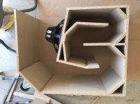
Looking at the photo of the prototype I just hope you left enough room for the excursion of the speaker cone. x-mech looks very close to hitting the internals.
Assuming that that is a single thickness of 18mm (3/4") for the baffle, and x-damage for the Faital 18HP1060 is 21mm.
Assuming that that is a single thickness of 18mm (3/4") for the baffle, and x-damage for the Faital 18HP1060 is 21mm.
Hi xoc1
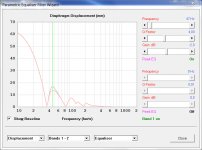
its exactly 19+2mm. have a look the gap. the prototype was only 19mm, so you were right. the sims and also the measurements are showing xmax is about 12mm at 47Hz with Pmax.
at 47Hz center we have a little hump, a correction of -2dB in this range brings xmax back to 9mm. i think loading is good, when testing the later versions we find out no problems with xmax. i hope we are far away from xdamage😉
btw: thank you for all the interesting posts. learned a lot
Attachments
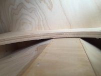
rectification: xmax is 12.5mm, the prototype was made with 19mm pressboard. please excuse my confusion. the grinding dust makes a little dizzy....
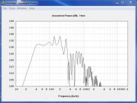
this simulations came very close to our measuring we did in different situations ( except the resonances above 100Hz).
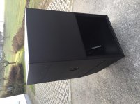
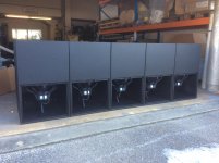
the main reason for the 18HP1060 was the best price/performance ratio. we do not targeting maximum output from a single box. what we want is the characteristic sound of the tapped horn. with a little EQing you can manage almost every setup. the fellows (300km away from me) already did a few smaller gigs with their cabs (see picture showing some of their cabs after painting and assembling) and they are very happy.
@xoc1: what do you think about?
this simulations came very close to our measuring we did in different situations ( except the resonances above 100Hz).
the main reason for the 18HP1060 was the best price/performance ratio. we do not targeting maximum output from a single box. what we want is the characteristic sound of the tapped horn. with a little EQing you can manage almost every setup. the fellows (300km away from me) already did a few smaller gigs with their cabs (see picture showing some of their cabs after painting and assembling) and they are very happy.
@xoc1: what do you think about?
Attachments
The cabinets look very professional. Should be a lot of fun to run them all together. How you are going to arrange all these cabinets?
The spec sheet says x-max is 12.45mm, which as we know is what we aim for, as once it is exceeded distortion starts to increase. But during 'rock & roll' this could be exceeded and probably will. It only takes an enthusiastic DJ, or an unlimited kick drum. The speaker should be designed to take dynamic transients as and when these occur.
I don't know if the EQ will be very helpful. A large signal at that 47Hz frequency will just drive the speaker as far as the amplifier can manage. I usually aim to sim a high pass filter that gives the same displacement below the lowest minimum as above. Final assessment of the filter should then be done by practical testing with visual inspection of what the speaker cone is actually doing.
Remember that the Danley TH118 has a double thickness baffle, so the dimension you have made 21mm would be nearer 36mm. You don't want the inner pleat of the driver to touch the cabinet. On some speaker designs where the clearance to the edge of the cone is minimal, small grooves are machined to avoid any chance of contact.
If nothing else could be done I would be tempted to add a packing piece between the driver and the baffle to increase the clearance. This would be more economical than replacing 36 cones when somebody drops the mic.
this would be vers simple to improve using a router and a copy ring. only a small cut of lets say 5mm in the Area of the triple-roll.
when we visualy tested (looking at the coil wires and measuring the movement) never have seen an excess of the cone movement also at extreme levels. we used dynamic signals and sine-waves. but we found out one thing: sinewave 31Hz@Pmax longer the 30 sec makes the coil smell��. no damage but not recommended.
the only pro of our clique is preparing some stacking options by using bass mangement software. i think most of the time we need 2 subs per side... we will see
Originally Posted by zettairyouiki
"Passive" in this context meaning that there isn't a plate amplifier bolted to the back of the subwoofer and power is delivered from a rack of amplifiers (Powersoft K8) elsewhere. The signal processing is certainly DSP and not a physical filter.
Well that's Not passive, it's Active ! People reading what BertlSound wrote, who don't know, might be misled. So best to point it out
- Home
- Loudspeakers
- Subwoofers
- TH-18 Flat to 35hz! (Xoc1's design)