Hi, i just finished my first design, a 18'' Fane Colossus 18XB in a 221L bass reflex box i designed.
Now i had the oportunity to check the response of my speaker in an anechoic chamber, and see the frequency response.
I'm trying different configurations of damping material inside and measuring the frequency response, so i can see and measure wich configuration will be best.
Now i upload the graphics, and when i get home i'll upload some pictures about the mounting and the box.
1.-
Blue line is with full damping material // green line no damping material
2.-
Blue line is with full damping material // green line with half damping material
I haven't got time to try more configurations, but hope i wil try to convince them to let me have some more fun.
Do you think is it good enough? Do you think i made a crappy design and should throw it to the bin? Any advices??
One question i have is, someone told me something about....(can't remember wel..) that if you want to measure frequency response of a subbass speaker, you have to be at "far field", not at 1m, like i've been doing. Can anyone explain me this please?
Here are the freq response with the hole span:
1.- No damping material
2.- Half loaded damping material (BACK AND UP)
3.- Fully loaded with damping material
Thx for your help in advance.
Don't be cruel, its my very first toy i make")
pd: measures done with good microphone (omnidir & flat resp) and Pulse Labshop
Now i had the oportunity to check the response of my speaker in an anechoic chamber, and see the frequency response.
I'm trying different configurations of damping material inside and measuring the frequency response, so i can see and measure wich configuration will be best.
Now i upload the graphics, and when i get home i'll upload some pictures about the mounting and the box.
1.-
An externally hosted image should be here but it was not working when we last tested it.
Blue line is with full damping material // green line no damping material
2.-
An externally hosted image should be here but it was not working when we last tested it.
Blue line is with full damping material // green line with half damping material
I haven't got time to try more configurations, but hope i wil try to convince them to let me have some more fun.
Do you think is it good enough? Do you think i made a crappy design and should throw it to the bin? Any advices??
One question i have is, someone told me something about....(can't remember wel..) that if you want to measure frequency response of a subbass speaker, you have to be at "far field", not at 1m, like i've been doing. Can anyone explain me this please?
Here are the freq response with the hole span:
1.- No damping material
An externally hosted image should be here but it was not working when we last tested it.
2.- Half loaded damping material (BACK AND UP)
An externally hosted image should be here but it was not working when we last tested it.
3.- Fully loaded with damping material
An externally hosted image should be here but it was not working when we last tested it.
Thx for your help in advance.
Don't be cruel, its my very first toy i make
pd: measures done with good microphone (omnidir & flat resp) and Pulse Labshop
If your response curves are correct, your "sub" is 20 dB down at 50 Hz from 250 Hz.Hi, i just finished my first design, a 18'' Fane Colossus 18XB in a 221L bass reflex box i designed.
Now i had the oportunity to check the response of my speaker in an anechoic chamber, and see the frequency response.
I'm trying different configurations of damping material inside and measuring the frequency response, so i can see and measure wich configuration will be best.
Now i upload the graphics, and when i get home i'll upload some pictures about the mounting and the box.
1.-
An externally hosted image should be here but it was not working when we last tested it.
Blue line is with full damping material // green line no damping material
2.-
An externally hosted image should be here but it was not working when we last tested it.
Blue line is with full damping material // green line with half damping material
I haven't got time to try more configurations, but hope i wil try to convince them to let me have some more fun.
Do you think is it good enough? Do you think i made a crappy design and should throw it to the bin? Any advices??
One question i have is, someone told me something about....(can't remember wel..) that if you want to measure frequency response of a subbass speaker, you have to be at "far field", not at 1m, like i've been doing. Can anyone explain me this please?
Here are the freq response with the hole span:
1.- No damping material
An externally hosted image should be here but it was not working when we last tested it.
2.- Half loaded damping material (BACK AND UP)
An externally hosted image should be here but it was not working when we last tested it.
3.- Fully loaded with damping material
An externally hosted image should be here but it was not working when we last tested it.
Thx for your help in advance.
Don't be cruel, its my very first toy i make
pd: measures done with good microphone (omnidir & flat resp) and Pulse Labshop
Frankly, I don't think you could have screwed it up that badly, I suspect the measurements are way off.
An anechoic chamber good down to below 150 Hz would have to be huge, and have many truckloads of fiberglass.
As far as damping, it seems to only have a slight negative effect in the range where a sub would be used.
Measuring a sub at more than one meter is more representative of the "real world", as large subs measured close appear to be more like 1/4 space than half space. Measuring at 100 watts at 10 meters rather than one watt at one meter is better when using subs that are "bigger than a bread basket".
Art
well... the anechoic chamber is from a university, it's quite big...maybe....10meters x 7meters.
The measures i don't think it's badly done, because i've checked again and again. And they also helped me.
I think the problem is, that maybe i have to do the measure 100W@10meters as you say?
Can it be possible that my design is not good enough and thats why i have so big difference between 50Hz and 250 Hz?
My design is :
638(W)x685(H)x519(D)
then i calculated a port length of 240 but tunning the system....to achieve a Fb of 36 i finally ended up trimming to 130, and achieving a Fb of 39-40. Do you think it is too high?
My answer to tunning up so high, is that hardtek music never has many really big subfreq below 38...And i was thinking that anyways with the Xover i would make the range for this something aroung 38-200Hz. Am I thinking wrong?
Well thanks a lot for you help, as always
Really appreciate it
pd: yes it is part of a PA i'm designing. (i'm a newbie that instead of copying a design, tryed to make one, and have some fun)
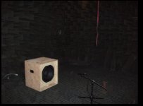
here you go a slideshow of all the building process, and some pictures about the measures.
ImageShack(TM) slideshow
ImageShack(TM) slideshow
7 meters is not acoustically large for low frequencies, that is the wavelength of 50 Hz.well... the anechoic chamber is from a university, it's quite big...maybe....10meters x 7meters.
The measures i don't think it's badly done, because i've checked again and again. And they also helped me.
I think the problem is, that maybe i have to do the measure 100W@10meters as you say?
Can it be possible that my design is not good enough and thats why i have so big difference between 50Hz and 250 Hz?
My design is :
638(W)x685(H)x519(D)
then i calculated a port length of 240 but tunning the system....to achieve a Fb of 36 i finally ended up trimming to 130, and achieving a Fb of 39-40. Do you think it is too high?
My answer to tunning up so high, is that hardtek music never has many really big subfreq below 38...And i was thinking that anyways with the Xover i would make the range for this something aroung 38-200Hz. Am I thinking wrong?
Well thanks a lot for you help, as always
Really appreciate it
pd: yes it is part of a PA i'm designing. (i'm a newbie that instead of copying a design, tryed to make one, and have some fun)
That is like testing a speaker with a 375 Hz bottom end in a one meter "room".
Your cabinet looks reasonable in size, bracing and porting.
I have 4 inch speakers in sealed cabinets that do better than 20 dB down at 50 Hz from 250 Hz.
Either their test results are wrong, or your speaker is broken.
Get a dB meter, set it down a couple meters (or 10 if you have wide open spaces) from the cabinet and run sine waves through at various frequencies and see and hear for yourself.
While you are at it, confirm the Fb is what you planned, the cone movement will be at minimum at Fb, and will increase rapidly below.
Last edited:
I mase a suspicion, but i might be wrong.
anyways, would you be so kind to do an impedance mesurement for Your sub?
range should be from 20 hz to 400 hz.
I em dying to see the result.
Allso, does the used microphone has a calibration graph available?
1.- They have a Cesva verification "tester" that emits 94db@1KHz , then i put the microphone inside, and measure with the software/hardware, if it is different from 94dB, due to the Pulse Labshop sensivity, i adjust de sensivity so it gives me 94dB. But as far as i know, this is only needed for the "sensivity response" right? So i have 2.82 V at the amplifier (1W) and the chain of measure is adjusted to 94 db @1kHz.
2.-I haven't got the curve done, because i haven't had time, but i did it without taking all values. Just moving the freq generator frequency knob and checking the minimum voltage between the 2 maximums.I'll try to get some time, and convince them i can go again, and take values one by one and make an excel graph, so you can see.
But for the impedance curve(graph), they told me to wait for the Audio precision so we can measure/draw it exactly.
Thanks again for all your help.
Either their test results are wrong, or your speaker is broken.
Get a dB meter, set it down a couple meters (or 10 if you have wide open spaces) from the cabinet and run sine waves through at various frequencies and see and hear for yourself.
While you are at it, confirm the Fb is what you planned, the cone movement will be at minimum at Fb, and will increase rapidly below.
hmmm
you mean that my driver is broken??? The box is air tight, and with silicon.
Can it be a problem of wrong design?
And i think, that now (like i did...) i can confirm, that with the stable wave generator with a sine wave output and a AC voltimeter (Fluke 187, so not cheap one.....like the one i tryed first...(my tester jeje)) And i measured a minimum around 38-39-40.
Nothing wrong with the design nor the build quality from what I can see from your pictures. It's much more likely a measuring error somewhere down the line.hmmm
you mean that my driver is broken??? The box is air tight, and with silicon.
Can it be a problem of wrong design?
And i think, that now (like i did...) i can confirm, that with the stable wave generator with a sine wave output and a AC voltimeter (Fluke 187, so not cheap one.....like the one i tryed first...(my tester jeje)) And i measured a minimum around 38-39-40.
(Btw Art, it's not the wall distances that set out the reference for an anechoic room but the efficiency of absorption in relation to its thickness (1/4WL) that set out the (bottom) limit for the LF of the anechoic room. So for example if you have absorption thickness of 1.71 meter that means 50Hz bottom limit of the room. I suppose your assumption is based on normal room acoustics (reflecting walls), which is definitely something else.)
Can their setup measure nearfield response for low bass?
The mic is really close to cone and /or port (ie a few mm), and no need for anechoic chamber to measure how the build matches modelled response. See D.B Keele JAES April 1974.
microphone is @ 1 meter from speaker.
But you "need" anechoic chamber to measure freq response, without going to a free space....or using softwares that kill reflection,etc right??
This evening, i'm going back, so i'll measure it again, and try with a sonometer to move around...., and get values one by one with an ACvoltimeter, so you i can plot the impedance curve of the bass reflex box. I'll have it done...in.... 5 or 7 hours from now.... (have to go to visit a friend first
)thx for all your help, really appreciate it
I agree that his cabinet looks OK.Nothing wrong with the design nor the build quality from what I can see from your pictures. It's much more likely a measuring error somewhere down the line.
(Btw Art, it's not the wall distances that set out the reference for an anechoic room but the efficiency of absorption in relation to its thickness (1/4WL) that set out the (bottom) limit for the LF of the anechoic room. So for example if you have absorption thickness of 1.71 meter that means 50Hz bottom limit of the room. I suppose your assumption is based on normal room acoustics (reflecting walls), which is definitely something else.)
That leaves a measuring error or a bad speaker to account for the lame LF response of the speaker. Almost looks like a pinched voice coil, like the speaker was dropped and the magnet shifted.
I don't think given the size of the absorption wedges that the room is anechoic down to anywhere near 50 Hz, which is why I suggested taking the speaker outside and testing it.
That said, a semi-anechoic room should not result in such little LF output.
Art
Attachments
Endrek, I have a few guidelines for you:
1.) Always measure crossways in an anechoic room (from corner to corner). This way the absorption is most effective and you don’t have parallel walls.
2.) There is no rule that says your mic needs to be pointed at the centre of the cone (often anywhere but pointing at the centre of the cone gives better results). Also micing in a anechoic room is much more sensitive for placement.
3.) Try to use an oscilloscope to ‘see’ the amplitude output signal of the amplifier (gives more reliable results than a multimeter).
4.) Every anechoic room should have a reference loudspeaker to check the equipment quickly. So ask if they have.
5.) Make sure the amplifier you use is load and frequency stable. I see they have Bruel and Kjaer equipment but what amp are you are using?
6.) 1 meter distance should be measured from the front baffle of the loudspeaker
7.) To calibrate for LF measurements you can’t use 1Khz as a reference signal (250Hz max)
8.) Read Epa’s post which means know your software and how to use it correctly.
9.) Every plot should come with information like: Used signal, distances, power ratings and used equipment.
2,83V measurements are not the same as 1watt. So keep your 2,83V setting and forget about the 1 watt
Endrek, I have a few guidelines for you:
4.) Every anechoic room should have a reference loudspeaker to check the equipment quickly. So ask if they have.
5.) Make sure the amplifier you use is load and frequency stable. I see they have Bruel and Kjaer equipment but what amp are you are using?
6.) 1 meter distance should be measured from the front baffle of the loudspeaker
7.) To calibrate for LF measurements you can’t use 1Khz as a reference signal (250Hz max)
2,83V measurements are not the same as 1watt. So keep your 2,83V setting and forget about the 1 watt
they don't have a reference speaker, they use this "http://datasheets.cesva.com/cb004_prt.pdf" to check the equipment. And then adjust the sensivity of the hardware/software of the Pulse Labshop so it's 94 db@1kHz.
The amplifier is a Ecler XPA3000, I did measure the voltage and change the frequency of the generator, and it was quite stable.
To calibrate the chain measure i use 250Hz@94db too???!?! or i have to look the isophonic curves, the value at 250Hz...etc?? i'm a bit lost
sorry for being newbie hehethx for all your help
pd: 2sqr(2) = 2,8284271247461900976033774484194 equals to 1 Watt right?? maybe its better aprox 2.83
i see hehe thx There reference is based on single frequency 1Khz point? Not very lab style and definitely not confirm any IEC or AES protocol for anechoic rooms. Strange a university is building an anechoic room and ‘forget’ about those standards.
The Ecler amps are stable enough for most measurements so that isn’t the problem.
The Pulse Labshop is certified Bruel and Kjaer equipment so I don’t think the equipment is the problem. The biggest problem with Labshop is the many different settings so make sure somebody around there knows what he is doing.
There are a few things you should check in the Pulse Labshop software and hardware because it looks like one of the filters is still on;
1.) Check if the low cut filter is off (I believe it’s standard on).
2.) Change the measuring bandwidth from 0Hz -20KHz to 0Hz – 250Hz or 0Hz to 500Hz (you do that in setup)
3.) Check if any “Edit / Add Transducer Type” is used wrongly.
4.) Check if the hardware module “Hammer” unit number is corresponding to the correct number in the software (“Edit / Add Transducer Type”) and that on the “hammer” the High Pass filter is turned off.
To calibrate the whole chain you need to read the manual cause I have no idea what you are using and what not. You need to make a drawing of your setup if you want more detailed info on that. Those Bruel and Kjaers are pretty complex setups for anyone, lot of settings that can go wrong. Using a labtop with a quality soundcard is way more easy to use.
About the 1 watt; you measure with either 1 watt (old fasion way) or 2,83V. If you choose for 1 watt and you are measuring with sine waves you need to calculate the corresponding Voltage. You need to measure the Re of the driver. In your case the Fane should measure around 6,5Ohm.
So 1watt = 2.5495V for that Fane driver.
You can use this calculator LINK
But like I said, forget about 1 watt, just measure with 2,83Volts since this is a standard. So in case you publish anything don't use the word Watt but state you measured with 2,83V and its okay.
I'll upload in a few minuts a setup draw.
I went today, but i couldn't measure the impedance curve and freq response. But i found the specification of the anechoic chamber, and says this :
(maybe here its the problem due to the cut frequency of the chamber)
-Volume with out damping material 517m^3
-Volume available 215 m^3
-Resonance Frequency 11Hz
-Cut Frequency 70Hz
-Isolation @1KHz 80dB
Does this mean that i won't be able to get a good response in this chamber below 70Hz????
- Status
- This old topic is closed. If you want to reopen this topic, contact a moderator using the "Report Post" button.
- Home
- Loudspeakers
- Subwoofers
- Check my First Box & Measure in anechoic chamber