This is a project to get "some" bass back in the house. I have been dealing with home speakers with diameters <4" ever since the sub was evicted and yesterday I was listening to Pink Floyd on 2.5" computer speakers  and that was the final straw! We had an 8" sub I built into a 47 liter ported enclosure for-e-ver ago, but it was kicked out of the house due to unacceptably low WAF and high risk of little fingers poking the cone after the grille was broken. I wanted to design this driver into a box that protects the cone without a grille, so bandpass here we come!
Driver: Dayton "Thruster" 295-160 (obsolete)
Qts 0.390 . Vas 37.1L . Fs 31.6Hz . Re 3.7 ohms
Le 0.9mH . Xmax 8.72mm . Z 4 ohms . Qms 10.54
Qes .410 . SPL 86.6dB (1W) . Pe 180W . BL: 9
Dia: 203cm . Sd 201.3cm^2
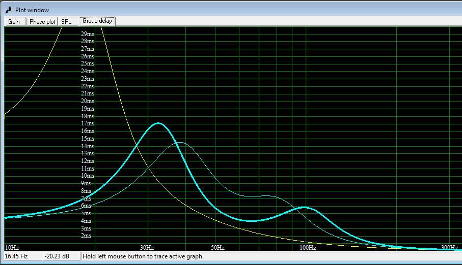
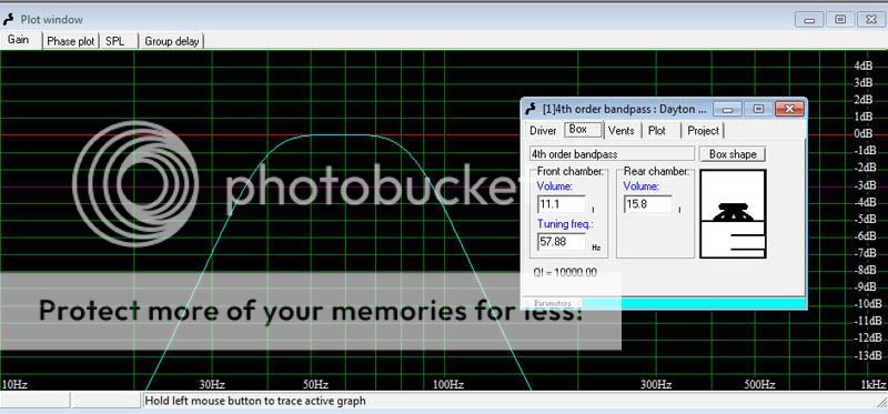
The narrow line is the "ideal" (highest gain) plot selected by WinISD and the thick line is what I currently intend to build. Yellow line is the old box this unit will replace. Don't be too hard on the old box - it was free!
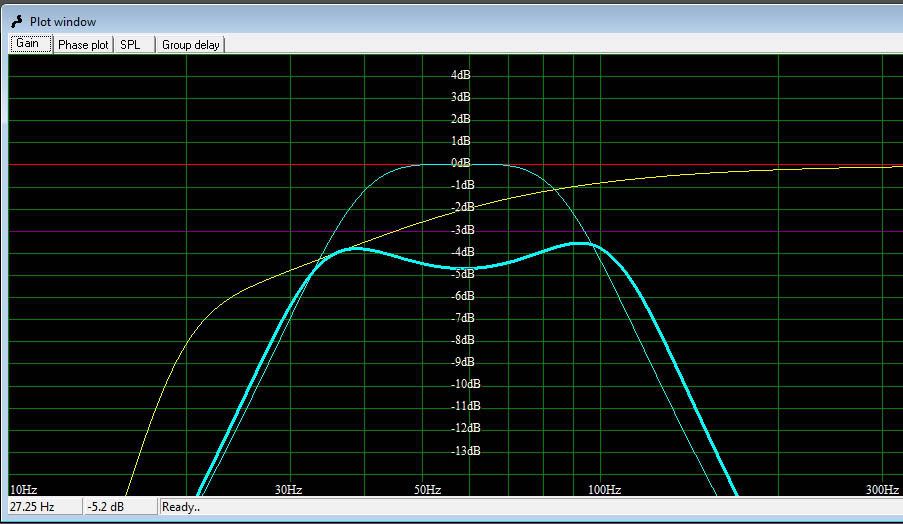
The gain plot looks like the old box wins for low frequency extension . . . until you plot the SPL output, and give the new box 2W and the old box 1W. That's what I call good enough for this project.
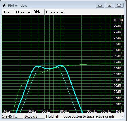
I can model it to go lower (even a LOT lower) but efficiency and high frequency extension go to pot and box size goes way, way, way up.
and that was the final straw! We had an 8" sub I built into a 47 liter ported enclosure for-e-ver ago, but it was kicked out of the house due to unacceptably low WAF and high risk of little fingers poking the cone after the grille was broken. I wanted to design this driver into a box that protects the cone without a grille, so bandpass here we come!Driver: Dayton "Thruster" 295-160 (obsolete)
Qts 0.390 . Vas 37.1L . Fs 31.6Hz . Re 3.7 ohms
Le 0.9mH . Xmax 8.72mm . Z 4 ohms . Qms 10.54
Qes .410 . SPL 86.6dB (1W) . Pe 180W . BL: 9
Dia: 203cm . Sd 201.3cm^2
The narrow line is the "ideal" (highest gain) plot selected by WinISD and the thick line is what I currently intend to build. Yellow line is the old box this unit will replace. Don't be too hard on the old box - it was free!
The gain plot looks like the old box wins for low frequency extension . . . until you plot the SPL output, and give the new box 2W and the old box 1W. That's what I call good enough for this project.
I can model it to go lower (even a LOT lower) but efficiency and high frequency extension go to pot and box size goes way, way, way up.
Last edited:
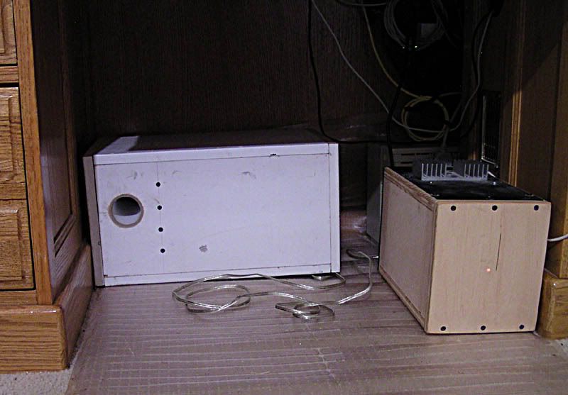
Progress! New hotness is the white on the right, old & busted is the big black one. The new box is almost exactly half the size of the old, and the woofer *barely* fits. Barely as in, I had to notch the sides about 1mm to give clearance for the driver's frame. Bandpass boxes are all about tradeoffs and this one sacrificed box depth in a big, big way. WAF should be infinitely improved: it could be placed behind the TV or under the desk, it's so small. Let's just hope it sounds decent!
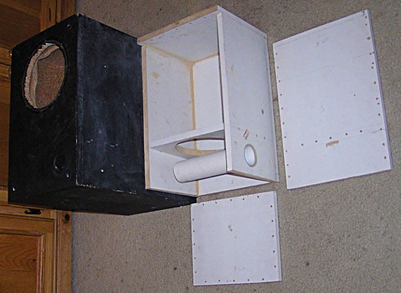
edit: looking at that picture you could get the wrong impression. The port is rounded on the inside and there is plenty of meat around the opening to get a good flare on the outside. The inside end is a solid couple of inches from the wall.
edit: looking at that picture you could get the wrong impression. The port is rounded on the inside and there is plenty of meat around the opening to get a good flare on the outside. The inside end is a solid couple of inches from the wall.
Last edited:
That thing is screwy!
There are screws every ~45mm or so, and they penetrate all of about 1cm. They don't go deep into the board, so I put a bunch to try to make up it. Before the boards are screwed together, a bead of silicone rubber is set on the inside edge of the contact area. When the boards are screwed down, what smooshes into the inside of the box is smoothed out by hand (and then it sucks sawdust to itself, which is why the sawdust colored lines in the corners).
The material is something like 5/8" MDF which to my mind is a step above cardboard for holding screws. The holes are predrilled on BOTH sides. I had forgot how easy it is to shape MDF with a file, and I don't want to find out again how easily a screw hole will strip out.
I'm not too worried about bracing in this box. Volume is limited by the driver to just over 100dB and that goes a very, very long way at our house.
edit: the holes out of line on some of the boards are from the last use. They don't penetrate through the other side. P.S. this is all reclaimed materiel except the glue & screws!
Last edited:
Before the boards are screwed together, a bead of silicone rubber is set on the inside edge of the contact area. When the boards are screwed down, what smooshes into the inside of the box is smoothed out by hand (and then it sucks sawdust to itself, which is why the sawdust colored lines in the corners).
Are you going to permanently attach the panel at the bottom? I suggest you don't - that vent will likely need to be trimmed.
I was going to use speaker basket gasket stuff on one side so I could go back in without too much trouble. The stuff is not squishy enough to let the box close properly. Then I figured what the heck, it's made of basically paper anyway, so I silconed the whole thing up tight. I'm not worried about the port. I don't have an RTA so I'll never know how bad it is "supposed" to sound and WinISD says this design is VERY tolerant of minor variances.
Anyhow, I did use the black speaker gasket stuff (like plasticene, I forget the name of it) on the driver. I pulled the wires off the connections at the driver while mounting the terminal on the outside AFTER closing the box, but fortunately the sealant was only half-cured and I could still pull the box apart easily.
Then my Wife said I need to get hot on something else that will take all my "finishing" time, so until the other project gets done, this is as finished as it gets. I plugged it up with the amp (in the wooden box, formerly a Klipsch bandpass sub plate amp, ironically enough) and let 'er rip.
The results: HUGE disappointment! I twiddled with settings and levels, couldn't figure out why it didn't sound different to before. I switched off the amp then - and the bottom octave just totally fell out of the music! I know it was supposed to be this way, but with the sub amp on, it has bass like I expected . . . and there is basically none with the amp off. Duh, me? Well I'll call it a victory for now and hope to finish the exterior of the box soon.
The sub amp has a variable crossover and I've set it for full band pass (<150Hz) so the sub can pick up the bottom of the midbass from the (frankly lacking) high speakers. If I turn the crossover frequency down there is a big hole in the midbass. I designed it to pick up the midbass and integrate with the highs like this so I'm pretty happy with the overall (sonic) result.
The aesthetics . . . oh well, at least it fits under the desk.
and WinISD says this design is VERY tolerant of minor variances.Anyhow, I did use the black speaker gasket stuff (like plasticene, I forget the name of it) on the driver. I pulled the wires off the connections at the driver while mounting the terminal on the outside AFTER closing the box, but fortunately the sealant was only half-cured and I could still pull the box apart easily.
Then my Wife said I need to get hot on something else that will take all my "finishing" time, so until the other project gets done, this is as finished as it gets. I plugged it up with the amp (in the wooden box, formerly a Klipsch bandpass sub plate amp, ironically enough) and let 'er rip.
The results: HUGE disappointment! I twiddled with settings and levels, couldn't figure out why it didn't sound different to before. I switched off the amp then - and the bottom octave just totally fell out of the music! I know it was supposed to be this way, but with the sub amp on, it has bass like I expected . . . and there is basically none with the amp off. Duh, me? Well I'll call it a victory for now and hope to finish the exterior of the box soon.
The sub amp has a variable crossover and I've set it for full band pass (<150Hz) so the sub can pick up the bottom of the midbass from the (frankly lacking) high speakers. If I turn the crossover frequency down there is a big hole in the midbass. I designed it to pick up the midbass and integrate with the highs like this so I'm pretty happy with the overall (sonic) result.
The aesthetics . . .
oh well, at least it fits under the desk.I was going to use speaker basket gasket stuff on one side so I could go back in without too much trouble. The stuff is not squishy enough to let the box close properly. Then I figured what the heck, it's made of basically paper anyway, so I silconed the whole thing up tight. I'm not worried about the port. I don't have an RTA so I'll never know how bad it is "supposed" to sound
Anyhow, I did use the black speaker gasket stuff (like plasticene, I forget the name of it) on the driver. I pulled the wires off the connections at the driver while mounting the terminal on the outside AFTER closing the box, but fortunately the sealant was only half-cured and I could still pull the box apart easily.
3/8" foam weatherstripping is the perfect gasket material, both for the side and the speaker, as it permanently bonds on only one side. It should be available from any hardware store. I use it for all of my builds.
One issue I've found with bandpass boxes similar to your design (i.e. those that include long vents) is that Fb can turn out to be lower than expected, which can drop the efficiency of the alignment quite a bit. The solution is to trim the vent until measurements suggest that the target Fb has been achieved.
I did think about a 6th order alignment but . . .
I'll take that as a compliment. It took a LOT (read: hours) of "tuning" in WinISD to come up with that plot. I did notice a strong similarity to the results when modeling a 6th order box, but the BP6 boxes were coming out larger with very long ports. That, plus the fact that there is one more hole waiting to receive a child's toy, plus the way a BP4 is more forgiving of slight variances, led me to decide on BP4 vs. BP6.
Bandpass designs are about tradeoffs, mostly bandwidth vs. efficiency. I chose bandwidth in this case. Like I said before, I did get it out into really low bass in the sims, but then efficiency REALLY fell off. If I remember I'll see about modeling some other designs and show y'all what I mean. I seem to recall (in the extremes) a corner in the low end extension somewhere around 15Hz, group delay literally off the chart, and a 500 liter box (remember this is a single 8" driver! ) at various stages in the modeling process. Oh, and ports 5 meters long.
Edit: oh, and re: trimming the port . . . you're right, but it is not gonna happen. It sounds decent and it brought the bass back into my listening experience. At this point, for this project ( $free, done in 3 days from idea to listening, for casual listening) I am entirely disinclined to do any finish-tuning at all. If it were a box I really wanted to sound just right, there would be a permanently-removable panel somewhere so I could get back inside. This one I just don't care enough about to go to the effort.
Last edited:
56k modem? You may want to come back in a few minutes
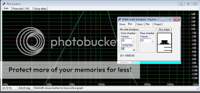
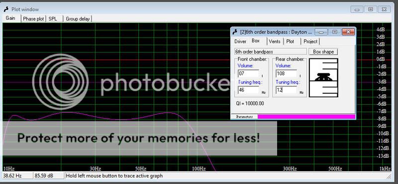
The "typical" curves from 4th order and 6th order bandpass boxes are pretty much all about the tuning of the box. A sealed box can be made to sound like a vented box sometimes, too, right? This is the same thing, with another vented box on the front of the woofer. The dip in the middle is a compromise between linearity, gain, and bandwidth. I preferred a little wider frequency response, and a 1dB dip on paper was found acceptable.
For grins, I played around in WinISD tonight and found that you can "theoretically" get the same modeled output from both alignments.
I found that I could get a perfect overlay of the graphs for frequency response, even in the same box size . . . provided you can somehow fit 2.6 kilometers of port length in the box!
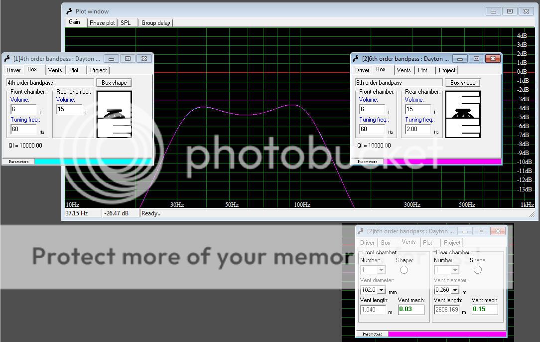
Amazingly, WinISD even claims that the group delay from that 2.6km of pipe is the same as 9" of pipe in the BP4 enclosure!
Here again is WinISD's preference for maximum gain without being a total one-note wonder, this time with box specifications:
To answer your question specifically, what I did to this box was to cut the front chamber almost in half, tune it a few hertz higher, and slice a little volume out of the back chamber. I found that a half-liter or even a liter plus or minus made very little difference in the projected response on this box.
Speaking of one-note wonders: remember how I keep saying bandpass boxes are about a tradeoff between gain and bandwidth? This is going the other way, for gain instead of bandwidth.
Taken to the opposite extreme, if you had a very sharp low-pass crossover you "could" use this driver to cover an octave and a half (on paper, please hold the tomatoes! )
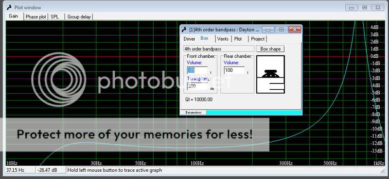
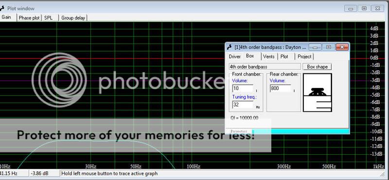
If you really want to tune it lower, you can . . . provided a rather large basement to house the rear chamber
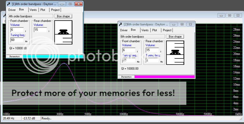
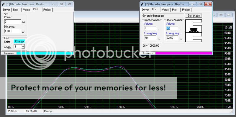
I also did a bit of playing with BP6 enclosures to further illustrate the point: Here we have very nearly identical frequency response, but note that the box I built has to have two watts to match the SPL output from the 6th order enclosure . . . one more port and a MUCH larger box. Oh, and the port for this one is "only" 12 meters long.
Now here is the one that really knocked me for a loop when I realized I was creeping up on it. How do you like a modeled output that's basically dead-flat from 9Hz to 90Hz? This driver, in a not-unreasonably-large-to-a-man box, can supposedly do it.
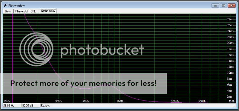
The group delay at and approaching the tuning frequency is typically high and has a big SPIKE for a 6th order bandpass box. This can be tuned out, on paper, but this one is a pretty dramatic example of the type. WinISD doesn't do cone excursion but it would probably be . . . interesting for this box.
Group delay for THIS modeled box in particular is pretty astonishing. That negative-going spike at 12Hz goes down to negative 29,600ms. Fortunately it's out of the audible range!
Okay, that's enough silliness for one night. I hope I have showed fairly well that bandpass boxes on paper can do amazing things, and even in practical wood-and-screws reality they can do a pretty good job if properly designed. . . and they MUST be properly designed, or there is a pretty good chance of adding one more example to the stereotype of bandpass = crap.
The "typical" curves from 4th order and 6th order bandpass boxes are pretty much all about the tuning of the box. A sealed box can be made to sound like a vented box sometimes, too, right? This is the same thing, with another vented box on the front of the woofer. The dip in the middle is a compromise between linearity, gain, and bandwidth. I preferred a little wider frequency response, and a 1dB dip on paper was found acceptable.
For grins, I played around in WinISD tonight and found that you can "theoretically" get the same modeled output from both alignments.
I found that I could get a perfect overlay of the graphs for frequency response, even in the same box size . . . provided you can somehow fit 2.6 kilometers of port length in the box!
Amazingly, WinISD even claims that the group delay from that 2.6km of pipe is the same as 9" of pipe in the BP4 enclosure!
Here again is WinISD's preference for maximum gain without being a total one-note wonder, this time with box specifications:
To answer your question specifically, what I did to this box was to cut the front chamber almost in half, tune it a few hertz higher, and slice a little volume out of the back chamber. I found that a half-liter or even a liter plus or minus made very little difference in the projected response on this box.
Speaking of one-note wonders: remember how I keep saying bandpass boxes are about a tradeoff between gain and bandwidth? This is going the other way, for gain instead of bandwidth.
Taken to the opposite extreme, if you had a very sharp low-pass crossover you "could" use this driver to cover an octave and a half (on paper, please hold the tomatoes! )
If you really want to tune it lower, you can . . . provided a rather large basement to house the rear chamber
I also did a bit of playing with BP6 enclosures to further illustrate the point: Here we have very nearly identical frequency response, but note that the box I built has to have two watts to match the SPL output from the 6th order enclosure . . . one more port and a MUCH larger box. Oh, and the port for this one is "only" 12 meters long.
Now here is the one that really knocked me for a loop when I realized I was creeping up on it. How do you like a modeled output that's basically dead-flat from 9Hz to 90Hz? This driver, in a not-unreasonably-large-to-a-man box, can supposedly do it.
The group delay at and approaching the tuning frequency is typically high and has a big SPIKE for a 6th order bandpass box. This can be tuned out, on paper, but this one is a pretty dramatic example of the type. WinISD doesn't do cone excursion but it would probably be . . . interesting for this box.
Group delay for THIS modeled box in particular is pretty astonishing. That negative-going spike at 12Hz goes down to negative 29,600ms.
Fortunately it's out of the audible range!
Okay, that's enough silliness for one night. I hope I have showed fairly well that bandpass boxes on paper can do amazing things, and even in practical wood-and-screws reality they can do a pretty good job if properly designed. . . and they MUST be properly designed, or there is a pretty good chance of adding one more example to the stereotype of bandpass = crap.
- Status
- This old topic is closed. If you want to reopen this topic, contact a moderator using the "Report Post" button.
- Home
- Loudspeakers
- Subwoofers
- New Bandpass Sub Build Thread