I'm glad to do design work for others in my spare time, I generally charge $35 per hour, which is a bargain compared to most professional services- I wish I could get a competent plumber for that price...not to burst your bubble or anything... but I very much doubt art has the time to draft up a subwoofer design he doesnt have much use for, esp since the keystone was a labor of MANY hours in the first place.
why not build the othorn?
That said, an existing, tested design is a guaranteed result (if well built), computer simulated designs are not, and the Keystone design would not have come about without extensive actual testing of multiple exit shapes and sizes.
Art
I didnt want to directly insinuate that some $$$ might sway your opinion, but I was pretty darn certain you wouldnt be interested in doing it for free (just didnt know what your rates where like, and didnt feel like guessing). $35 an hour is very reasonable.
Going to a lower tuning in the same size cabinet lowers voltage sensitivity.
Also when lowering tuning excursion demands go up even if you make the cabinet bigger to try and get back some of the sensitivity.
2- 15TBW100-8's in 1 cabinet, you could try 1- 21SW152-4"?
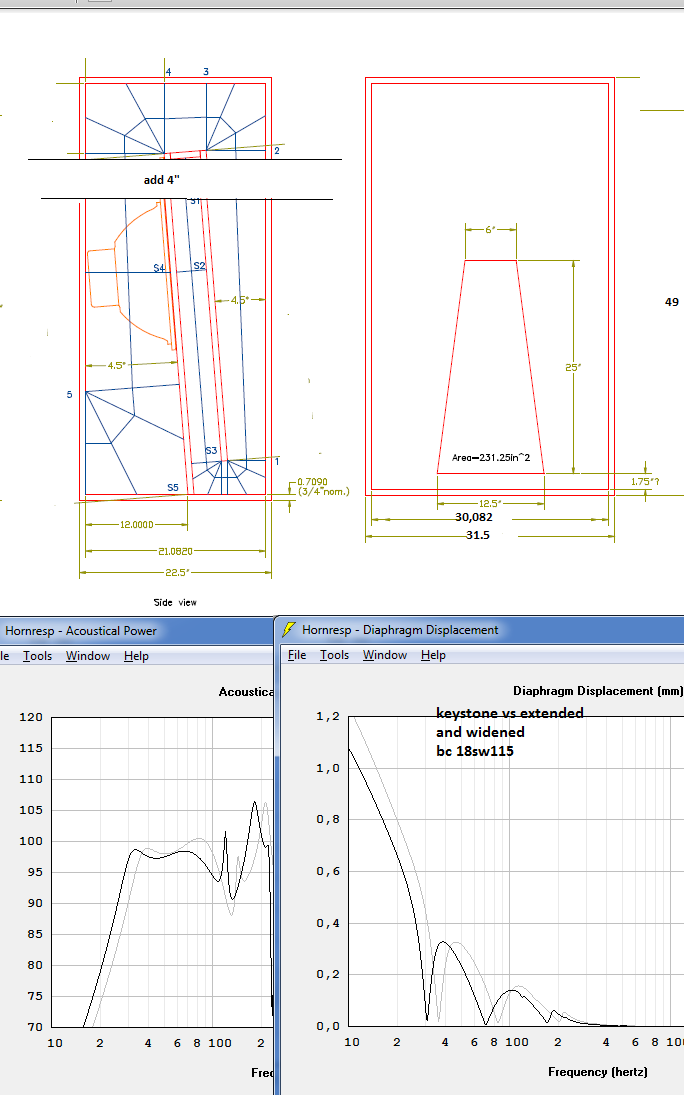
Art said in his response to me that the Keystone design could be made taller for a longer path length to extend the frequency response lower. That sounds like he is willing to help with a extended cab of his Keystone design. If not then I will surely look at great cabs like Josh's. Art,I like NEO DAN'S advice in using the 21SW152 driver. What about using this driver in a extended path length cab 30-32hz and not having to increase the width?
Thanks to all, hoping to not rock the boat, knowing that this design has been established.
hi 85audio
fwiw
if you make the box 4" taller and 5"wider it wil go ~5hz lower .
if you take the 21sw152-4 vs the 18sw115-4 excursion wil be the same.
(note this is simulated not measured,and doesn't include what the keystone exit does)
if art alows i can draw it up for you.
fwiw
if you make the box 4" taller and 5"wider it wil go ~5hz lower .
if you take the 21sw152-4 vs the 18sw115-4 excursion wil be the same.
(note this is simulated not measured,and doesn't include what the keystone exit does)
if art alows i can draw it up for you.
hi 85audio
fwiw
if you make the box 4" taller and 5"wider it wil go ~5hz lower .
if you take the 21sw152-4 vs the 18sw115-4 excursion wil be the same.
(note this is simulated not measured,and doesn't include what the keystone exit does)
if art alows i can draw it up for you.
That sounds good, dementionlly that's not much bigger. Are you saying that the 21SW152 is not necessary? That would be good because that driver is expensive.
Thanks
Nothing wrong with that idea, other than someone interested in building the Othorn just mentioned the driver is out of stock for quite some time. I have not verified stock.Art,I like NEO DAN'S advice in using the 21SW152 driver. What about using this driver in a extended path length cab 30-32hz and not having to increase the width?
I don't mind anyone posting up different designs, if EPA wants to, fine by me.
Art
to make things clear.
the "extended" keystone with the bc 21sw152 goes 5hz lower and wil have -2~3 db less output than the "normal" keystone with bc 18sw115.
excursion remains the same.
the "extended" keystone with the bc 21sw152 goes 5hz lower and wil have -2~3 db less output than the "normal" keystone with bc 18sw115.
excursion remains the same.
i wil do so if 85audio want'sI don't mind anyone posting up different designs, if EPA wants to, fine by me.
Art
Last edited:
Damn, your awesome man!I Thanks. And thanks Art for allowing this to happen. I'm going to look over the grafs better when I get home from work.
Shaun
What would a double Radian 2216 Keystone cab look like? 6" wider and still fit through the door. Is the 2216 a candidate, 14lbs apiece, light weight and 21.3mm xmax! I know, expensive, right. Who cares, what can it do.
Unfortunately, that Xmax specification is peak-to-peak, AFAIR.
I'm new at this so whatever measurements I make - take with a grain of salt. Panel flex would not surprise me - the cab vibrates a lot. Overall the construction is pretty tight though. The 3/16 gap at the top right face panel section is the worst one on the box (oops) - cut everything with a skill saw and carbide blade. I used TiteBond, deck screws, and sub floor adhesive to seal all joints so no air leaks or rattles.
It's pretty difficult to get an impedance measurement wrong (particularly if you're using something like the WT3 to do it).
The curve also suggests that you got the seal right, particularly around the driver and the first section of the horn. A small leak around that point would have made a significant difference to the shape and location of the lowest impedance peak.
The impedance curve does suggest though that there's room for improvement between 70 Hz and 100 Hz, most likely via some additional bracing. Running a 70 Hz tone through the subwoofer, and then adding bracing to the panel that's vibrating the most may be all that's needed to push the impact of panel flex outside of the subwoofer's passband.
How tolerant of TS params is the keystone design? Reason being that dump of 4ohm modified Lab 15s would mean a dual 15 loaded keystone could potentially put out some serious dirt cheap bass. I'm trying to run the hornresp sims myself, but this is the first time I've used it and I haven't yet gotten it to work right.
Special Lab 15 vs. (Lab 12)
Re = 3.75 Ohms (4.29)
Le = 1.60 mH (1.48)
Fs = 34.4 Hz (22)
Vas = 93.3 l (124.6)
Qms = 3.76 (13.32)
Qes = 0.59 (.39)
Qts = 0.51 (.38)
Xmax = 13.02 mm (13)
Sd = 823.7 (506.7)
BL = 17.47 ? Tm (15)
Since dual Lab12s is a suggested driver, I've compared the parameters.
If the dual Lab 12s is a solid option, would a widened dual special run Lab 15 cab do well?
It's pretty difficult to get an impedance measurement wrong (particularly if you're using something like the WT3 to do it).
The curve also suggests that you got the seal right, particularly around the driver and the first section of the horn. A small leak around that point would have made a significant difference to the shape and location of the lowest impedance peak.
The impedance curve does suggest though that there's room for improvement between 70 Hz and 100 Hz, most likely via some additional bracing. Running a 70 Hz tone through the subwoofer, and then adding bracing to the panel that's vibrating the most may be all that's needed to push the impact of panel flex outside of the subwoofer's passband.
Thank you for your analysis. I will try as you suggest and see what happens.
I did some tests with REW but didn't take good notes so can't post yet. I seem to have a dip from 70 to 90hz. Not complaining though – I know horn was designed for B&C driver. I am happy the cab sounds as good as it does w/Low Rider18
BTW what would be a meaningful distance for measurement mic and drive voltage level to yield useful data ?
Hi tralfaz,
If you have the chance could you measure the TSP's for the Lowrider with REW? I measured one many moons ago and was very disappointed by the results. Hopefully they have brought them back to spec.
Here's how I rank driver strength (BL²/Re)/Sd)
Sd is CM²/1000, so 1,210=1.21
Lab 12- 103.5
Lab 15- 98.8
18SW115-4- 150.49 My TSP's below
21SW152-4- 193.8 Per Data-Bass TSP's
Code:
Re         =    3.3665 ohms
Fs         =   30.7213 Hz
Zmax       =   84.2471 ohms
Qes        =    0.2989
Qms        =    7.1805
Qts        =    0.2869
Le         =    1.3210 mH  (at 1 kHz)
Diam       =  392.5073 mm  ( 15.4530 in  )
Sd         =121000.0068 mm^2(187.5504 in^2)
Vas        =  197.9838 L   (  6.9917 ft^3)
BL         =   24.7592 N/A
Mms        =  281.9458 g
Cms        =   95.1907 uM/N
Kms        =10505.2334 N/M
Rms        =    7.5793 R mechanical
Efficiency =    1.8047 %
Sensitivity=   94.5821 dB @1W/1m
Sensitivity=   98.3412 dB @2.83Vrms/1m
Krm        =   4.045E+00 ohms     Freq dependent resistance
Erm        =   0.000E+00          Rem=Krm*(2*pi*f)^Erm
Kxm        =   8.643E+00 Henries  Freq dependent reactance
Exm        =   0.000E+00          Xem=Kxm*(2*pi*f)^Exm
;------------------------------------------------------------------
Ftest                   =    22.888 Hz
Ftest/Fms               =    0.7450
Test Mass used          =  226.0000 g (Equal to 45.2 nickels)
Test Mass (Ft=Fms*0.90) =    66.135 g (Add -159.865g for Ft=27.649)
Test Mass (Ft=Fms*0.75) = 219.291 g (Add -6.709g for Ft=23.041)BTW what would be a meaningful distance for measurement mic and drive voltage level to yield useful data ?
Now you're opening up a whole other kettle of fish, LOL. Techniques for measuring FR vary widely, depending on what you're measuring and what you have available to perform the measurement.
For something the size of the Keystone sub, the 10M @28.3V approach may be the best one, but that of course requires you to have access to a huge flat area with nothing else closer to the sub. Something like a football field, for example.
For most people, that might be difficult to arrange.
This is why I tend to focus more on impedance measurements. Much easier to do, the results are very repeatable, and in some ways are actually of more value. And if course if the measured impedance curve is a good match for the predicted one, there's a pretty good chance that the actual FR will also be a pretty good match for the predicted FR.
I was measuring in a parking lot in an urban area and the SPL levels were an issue so I backed down to 100w, 20v @ 10m for my 4 ohm 18SW115-4 TH. That's still REALLY LOUD, dogs in the surrounding 1/4 mile went absolutely nuts.
I was measuring in a parking lot in an urban area and the SPL levels were an issue so I backed down to 100w, 20v @ 10m for my 4 ohm 18SW115-4 TH. That's still REALLY LOUD, dogs in the surrounding 1/4 mile went absolutely nuts.
LOL - Pink noise, or sine sweep, and how long was each measurement signal?
- Home
- Loudspeakers
- Subwoofers
- Keystone Sub Using 18, 15, & 12 Inch Speakers