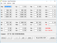
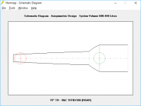
Hang on a bitwhat 15" design are we talking about here? ROAR15's external dimensions volume is 390dm3.
From the images of the sim posted in post #114. I entered the parameters into HornResp, and got this:
Attachments
The posted 600 liter simulation is a stock THAM15 (not 600 liters) and an add on foldable resonator (only a few liters when folded together for transport - as the other horn-extenders in this thread).
Do you compare the simulated volume of the Horn extender/Wave guide for all the designs discussed in this thread with other THs? I proposed the front resonator as an horn extender - as per the main topic in this thread.
I don´t understand why you suddenly want to compare non-extended THs with a stock THAM15 with a add on front resonator?!
No of course not, but I believe the engineers at Dbx saw a need for this feature. I don´t consider 48 dB/octave extreme or unnecessarily steep in any way. With all the DSP-power being baked into amps and processors these days, 48 dB/octave crossovers, DSP-based EQ, phase-adjustments and delay is all useful tools to maximize the performance of pro audio gear.
In a few years we will probably routinely compensate for all the group-delay with DSPs. You can´t use DSP to compensate for warped cones, scraping voice-coils and other artifacts from to high compression.
Do you compare the simulated volume of the Horn extender/Wave guide for all the designs discussed in this thread with other THs? I proposed the front resonator as an horn extender - as per the main topic in this thread.
I don´t understand why you suddenly want to compare non-extended THs with a stock THAM15 with a add on front resonator?!
Just because it's an option doesn't mean that it should be used
No of course not, but I believe the engineers at Dbx saw a need for this feature. I don´t consider 48 dB/octave extreme or unnecessarily steep in any way. With all the DSP-power being baked into amps and processors these days, 48 dB/octave crossovers, DSP-based EQ, phase-adjustments and delay is all useful tools to maximize the performance of pro audio gear.
In a few years we will probably routinely compensate for all the group-delay with DSPs. You can´t use DSP to compensate for warped cones, scraping voice-coils and other artifacts from to high compression.
Hi Johannes, not sure I understand what a THAM15 connected to front-resonator will look like. Will it be a THAM15 extended with a ROAR15 cabinet ?
I did have a look at the ROAR range in the link you provided. If you can please post a picture of THAM15 connected to a front-resonator. The sim looks good, thanks.
I did have a look at the ROAR range in the link you provided. If you can please post a picture of THAM15 connected to a front-resonator. The sim looks good, thanks.
I have never tested a THAM15 with a frontresonator so I don´t have any pictures.
It is a simple large duct attached to the front of a THAM15. 4 pieces of plywood held together with hinges in the four corners. All attached somehow to the front of the THAM.
I made some crude simple measurements of my ROAR12 today. I have just started playing with REW and my Umik. I got the microphone yesterday, so I have not had time to learn much yet. Please excuse any noob-mistakes, of which I am sure there are plenty...

The driver (B&C 12PS100) is brand new. I have been plying some low level music through it for an hour or two. Once the suspensions are soften by use, the low end of the passband will increase in level. The suspension feels rock hard at the moment.

It is a simple large duct attached to the front of a THAM15. 4 pieces of plywood held together with hinges in the four corners. All attached somehow to the front of the THAM.
I made some crude simple measurements of my ROAR12 today. I have just started playing with REW and my Umik. I got the microphone yesterday, so I have not had time to learn much yet. Please excuse any noob-mistakes, of which I am sure there are plenty...
The driver (B&C 12PS100) is brand new. I have been plying some low level music through it for an hour or two. Once the suspensions are soften by use, the low end of the passband will increase in level. The suspension feels rock hard at the moment.
Last edited:


4 pieces of plywood held together with hinges in the four corners
Or you could build the large duct/front resonator as a large box with one side open and a large cutout on the other side of the "box". This way it would be easy to transport the THAM15 inside the duct, and just mount the duct onto the front of the THAM15 when you are rigging the soundsystem.
Cheers,
Johannes


(These measurements are made with a raw driver and does not portray the real ROAR12 response.)
Here are two better measurements.
In the spl-response I show the raw response of the ROAR12 (red trace) with the new and raw driver, which needs several hours of 500 watts program power to loosen up.
The green trace shows the response with a 48 dB/octave 30 Hz HP and 48 dB/octave 180 Hz LP filters. All the filtering implemented with a MiniDSP 2X4HD.
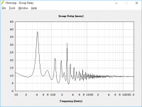
Even though there is a 13.6 ms hump at 168 Hz I would not hesitate to use this ROAR12 up to 180 Hz.
The group delay graph shows the same with or without steep crossover bandpass-filtering typically used in live pro use.
I post this as an example of a front-resonator enhanced tapped horn (tapped pipe in this example).
I hope I can test a THAM10 with a large front resonator soon.
I will post measurements with and without the resonator when I have them.
Cheers,
Johannes
would the ROAR family benefit from the addition of a resonator
ROAR is already a resonator enhanced tapped pipe. I can´t simulate adding another resonator since I don´t know how to use Akabak. I guess it would compound the groupdelay into excessive amounts.
Martinsson's Blog - ROAR18
No thread about the ROAR-family yet. I am trying to measure and validate the ROAR12 and thereby the whole ROAR-family, before we post dedicated threads about them.
Anders Martinsson has the complete ROAR-family on his blog.

Here is a simulation of the B&C 18DS115 in a ROAR18.
Its simulated in 2.0 Pi with 2.83 volt.
Quite impressive performance from a single 18 inch driver.
Cheers,
Johannes
Dumb question: wouldn't it save A LOT of pack space if you would construct the ROAR cabinet WITHOUT the resonator and then add the resonator as an add on? Of course this means a redesign of the cab...ROAR is already a resonator enhanced tapped pipe.would the ROAR family benefit from the addition of a resonator
Very interesting design, by the way
 . I'm waiting for the new frequency response curves with a broken in driver to see if the low end has picked up .
Hi Thijs666,
Ever heard a Stage Accompany XL-bin?
Same principle...
Regards,
Djim
Hi Djim,
Do you mean that the XL-bin uses the same principle as the ROAR? I'm not so sure of that. Looks like in the XL-bin the 'horn' part (where the front of the cone radiates into) is not really a horn but rather a bass reflex tunnel and it doesn't couple into the front resonator like in the ROAR, it just ends at the front of the box. At least that's what I could make out in the rather small google image results.
Anyway, I'm still looking to come up with a idea for a 'compact' sub that still goes loud and low, that's why I thought of the idea of a solid construction without the massive resonator...
I have just posted in the PA section in regards to using concrete boundaries to create pattern control and decrease low-frequency energy to the sides and rear of a stage position (angry neighbors...).
This waveguide idea may do the trick if built large enough, out of concrete and also possibly add treatment around the sub in the rear as well. If I can get significant directivity around a 90deg pattern this sounds like the answer. The baffles would be permanent concrete and the sub would get strapped into the port at the rear. How large would the baffle system need to be for say effectively down to 50hz?
Here is the other post (which I may delete) for reference.
"I have been doing a few shows in an outdoor venue and they have had lots of noise complaints from the surrounding residents. They are thinking they may pull the pin on having any future shows there anymore.
I have been trying to find out if it is possible to use acoustics/buildings and surfaces to steer the bass from conventional subwoofers out into the bay and minimize the coverage to the sides to our neighbors.
The venue is outdoors and one side faces out over a cliff and into an empty bay/river system. The potential plan is to use the existing large building (with modification) to create an acoustic shield around the stage so that it directs the low-frequency sound energy to hopefully a 90deg pattern into the crowd, then out into the bay.
I was considering cardioid subwoofers or arrays but I'm not sure how well they fare when backed up against a big building and a better solution may be the building acoustics itself with concrete baffles or something.
If I can organize to create some concrete baffles to direct the reflected subwoofer energy how big would they need to be to reduce the effect of having the low energy sound waves bend around the edges? Or does this only work if all sides are closed off by acoustic barriers right down to the bay edge?
The mid/top frequency range should not be a problem if we move to something like Danley speakers with great pattern control. Its the low frequencies that I am not so sure about...
If anyone has any experience or knowledge can you help point me in the right direction, is this idea possible or am I better off just going cardioid or giving up?"
There is no residences out on or across the open water and the maximum catered size of the sound system would be for 800people at most. The venue has a whole bunch of distributed speakers that this system will be hooked into so FOH won't be used at high volumes to cover the whole venue.
Here is a maps view with a bit of info. I roughly drew in the stage. From looking at things the far side guest rooms won't be as much of an issue due to distance so less directionality may be ok, its more just the rear of the stage that presents the biggest problem.
Mangrove aireial drawing.jpg - Google Drive
I am still keen on the idea of concrete FOH barn doors but I don't have much to back up this idea at the moment. I can't find much info on the web about this sort of thing. I am slowly researching more into this idea.
I was told by a Danley employee that "Here's a quick and dirty formula for you:
1,000,000 / inches / degrees gives the frequency at which a horn starts to lose pattern control."
By that calculation about 7m at 90deg would be about 7m which seems doable for this system.
My hesitation with cardioid arrays and subs is that it doesn't seem ideal for the broad range of low frequency I need (40-200hz evenly) and it does not seem to be that cost effective. this will be a permanent setup and system so building for directionality in mind may be the way to go.
Here is looking out from the stage area
20170719_135559.jpg - Google Drive
and looking into the stage area
20170719_135505.jpg - Google Drive
and the whole folder of images
Mangrove Hotel - Google Drive
As far as I am aware and from playing with it Danley direct does not calculate acoustics and only simulates speaker interaction outdoors. I would want to simulate the concrete barriers which I have looked at and I don't think it is possible. It does help with choosing the best speakers to use though.
Horn exit vertically or summed
Hi Art,
loving the 2 keystones I've built so far.
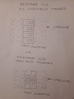
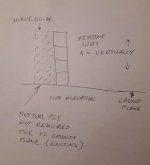
Question: see attached sketches - would there be a slight increase in summation / SPL if the horn exits were together as opposed to just vertically stacked?
I'm progressing and building another 2 for a total of 4, and adding waveguides for a mono stack.
I plan on tieing the bottom waveguides, of the stack, together with a box section of aluminum tube - as I believe the ground plane eliminates the need for another ply boundary.
Thoughts ? - cheers Art
Hi Art,
loving the 2 keystones I've built so far.
Question: see attached sketches - would there be a slight increase in summation / SPL if the horn exits were together as opposed to just vertically stacked?
I'm progressing and building another 2 for a total of 4, and adding waveguides for a mono stack.
I plan on tieing the bottom waveguides, of the stack, together with a box section of aluminum tube - as I believe the ground plane eliminates the need for another ply boundary.
Thoughts ? - cheers Art
Attachments
There is no residences out on or across the open water
Would that be Roebuck Bay, perhaps?
.- Home
- Loudspeakers
- Subwoofers
- Horn Extender/Wave-guide for TH