There have been various claims regarding the directivity of tapped horns, but since I had not seen any tests done comparing them to bass reflex (BR) or standard front loaded horns (FLH), I did some testing myself.
As suspected, TH in themselves have little more directivity than other types of cabinets below around 60 Hz, but do become more narrow in dispersion above.
The LF directivity others have noted when TH are used in multiples comes primarily from the increased frontal area acting as a plane, transitioning from 1/2 space to 1/4 space. This same effect happens to some extent with any type of speaker.
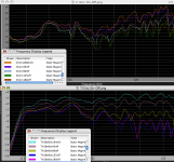
The BR is basically omnidirectional within about 1 dB to 60 Hz, then drops about 3 dB at 125, and around 7 dB at 160 Hz at 180 degrees off axis (behind the speaker).
The C horn is basically omnidirectional within about 3 dB to 60 Hz, then drops about 7 dB at 125, and above.
The TH is basically omnidirectional within about 2 dB to 60 Hz, then drops about 12 dB at 125, and around 9 dB at 160 Hz.
The TH with the extender shows the advantage of a large frontal area, it has some directivity all the way down to below 30 Hz. At 60 Hz, it has around 7 dB difference, and 125 Hz, a bit over 14 dB. A huge directionality increase from a sheet of plywood.
The BR cabinet and the TH both used the same BC18SW115-4 18” speakers, the C horn an EVX150A 15”.
The C horn is a spiral horn about 1.65 meters long, the TH is also a spiral around 3 meters long.
Tests were done with the microphone 10 meters from the front of the cabinet, the cabinet was rotated around the center of the cabinet front so the distance from the exit to the microphone was always 10 meters.
Tests were made on axis, 45, 90,135, and 180 degrees off axis, 180 off axis the cabinet is pointing away from the microphone.
In the case of the TH with the horn extender, the extra width of the cabinet would make the microphone distance to the cabinet center a portion of one meter longer when at 180 degrees than the other cabinets.
Cabinet dimensions are height, width, depth in inches:
BR 36 x 24 x 17.5
C Horn 26.5 x 22.5 x 30
TH 45 x 26.5 x 22.5
TH with extender 56.25 x 53 x 37.5
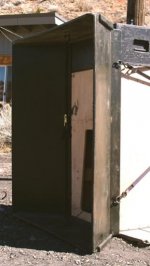
The extender is a simple 90 degree “wave-guide”, 45 degree each side, parallel top and bottom. A dummy cabinet was placed above the TH cabinet to cover the “hole”.
As it turns out, buildings and fences, even though more than 10 meters from the cabinet and test microphone had some fairly significant effects on the test, in most cases the 135 degree results were lower than the 180 degree, odd to say the least. A pump house (10 x 8 x 8 feet), located about 10 meters from the test microphone makes the response look “lumpy”, the cabinets all have quite smooth response when tested at 2 or 3 meters.
The surroundings make the tests flawed, but the flaws apply to all the cabinets.
Art
As suspected, TH in themselves have little more directivity than other types of cabinets below around 60 Hz, but do become more narrow in dispersion above.
The LF directivity others have noted when TH are used in multiples comes primarily from the increased frontal area acting as a plane, transitioning from 1/2 space to 1/4 space. This same effect happens to some extent with any type of speaker.
The BR is basically omnidirectional within about 1 dB to 60 Hz, then drops about 3 dB at 125, and around 7 dB at 160 Hz at 180 degrees off axis (behind the speaker).
The C horn is basically omnidirectional within about 3 dB to 60 Hz, then drops about 7 dB at 125, and above.
The TH is basically omnidirectional within about 2 dB to 60 Hz, then drops about 12 dB at 125, and around 9 dB at 160 Hz.
The TH with the extender shows the advantage of a large frontal area, it has some directivity all the way down to below 30 Hz. At 60 Hz, it has around 7 dB difference, and 125 Hz, a bit over 14 dB. A huge directionality increase from a sheet of plywood.
The BR cabinet and the TH both used the same BC18SW115-4 18” speakers, the C horn an EVX150A 15”.
The C horn is a spiral horn about 1.65 meters long, the TH is also a spiral around 3 meters long.
Tests were done with the microphone 10 meters from the front of the cabinet, the cabinet was rotated around the center of the cabinet front so the distance from the exit to the microphone was always 10 meters.
Tests were made on axis, 45, 90,135, and 180 degrees off axis, 180 off axis the cabinet is pointing away from the microphone.
In the case of the TH with the horn extender, the extra width of the cabinet would make the microphone distance to the cabinet center a portion of one meter longer when at 180 degrees than the other cabinets.
Cabinet dimensions are height, width, depth in inches:
BR 36 x 24 x 17.5
C Horn 26.5 x 22.5 x 30
TH 45 x 26.5 x 22.5
TH with extender 56.25 x 53 x 37.5
The extender is a simple 90 degree “wave-guide”, 45 degree each side, parallel top and bottom. A dummy cabinet was placed above the TH cabinet to cover the “hole”.
As it turns out, buildings and fences, even though more than 10 meters from the cabinet and test microphone had some fairly significant effects on the test, in most cases the 135 degree results were lower than the 180 degree, odd to say the least. A pump house (10 x 8 x 8 feet), located about 10 meters from the test microphone makes the response look “lumpy”, the cabinets all have quite smooth response when tested at 2 or 3 meters.
The surroundings make the tests flawed, but the flaws apply to all the cabinets.
Art
Attachments
Last edited:
One other finding in the course of over an alphabet's worth of different mouth shapes and trying various corner ramps was that adding corner ramps just changed some minor frequency dips and peaks in frequency.Very nice findings and good side info, thanx...
I guess a plane (non expanding) extension will work also but maybe less below a certain freq.
I ended up using no corner ramps at all in the Keystone TH design.
Art
Lol, Art it looks like this corner "thingy" is going to hunt me forever around here...
Anyways, they can have a more effective change when the corner is situated on the right spot. That’s why findings are so different. But sure they can give changes (even its minor) in the higher regions of the band pass. But still, I prefer to see them more as corner corrective tools instead of anything else...
Btw can you produce 360 degree graphs of your directivity findings?
The Smaart graphs I posted covered 180 degrees, in retrospect rotating the speakers the opposite direction as well (for 360 degrees) would have given some more useful data points, since the test environment was not symmetrical. I suspect readings at 225 dergrees, pointing more away from the backyard fence would show a greater reduction than the 135 and 180 graphs.Lol, Art it looks like this corner "thingy" is going to hunt me forever around here...
Anyways, they can have a more effective change when the corner is situated on the right spot. That’s why findings are so different. But sure they can give changes (even its minor) in the higher regions of the band pass. But still, I prefer to see them more as corner corrective tools instead of anything else...
Btw can you produce 360 degree graphs of your directivity findings?
That said, with the flawed test environment, I don't think I'll bother trying for more directivity tests.
I am still a bit amazed how much effect the distant surroundings had on the findings, looks like when the test microphone is 10 meters from the sub, 30 meters or more to buildings may be needed for test results to be valid.
I would not know where to start that book, not including the directivity tests, several weeks of sims with Hornresp, I conducted tests on at least 60 actual (plywood, sawdust, and lots of clamps) versions of the Keystone sub.Hey Art, not to be a choosy beggar, but is there a writeup of the "Keystone" forthcoming? Your comments regarding reflectors and mouth geometry hint at volumes of background info.
There are still a few more to do...
The funny thing (ha ha) is the design basically ended up being one I drew on the back of an envelope before downloading Hornresp.
The funny thing (ha ha) is the design basically ended up being one I drew on the back of an envelope before downloading Hornresp.
 I've had this very thing happen to me before. I let my analytical mind lead me away from my initial concept only to end right back where I started. Its the darnest thing. LOL.
I finally had a somewhat calm warm day to do a bit of testing, so I could add in directivity tests for the SS15.
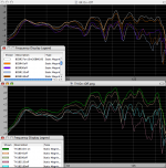
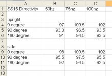
The interesting numbers are what happens to directivity as you lay it on it's side. (the 50hz reading is not a typo, I did it a couple times, just to make sure....)
This is single cabinet, sine waves, 10 meter test, over 100' from any buildings, etc... (not calibrated to 28v or anything, just turned up enough to test)
Attachments
Last edited:
I finally had a somewhat calm warm day to do a bit of testing, so I could add in directivity tests for the SS15.
The interesting numbers are what happens to directivity as you lay it on it's side. (the 50hz reading is not a typo, I did it a couple times, just to make sure....)
This is single cabinet, sine waves, 10 meter test, over 100' from any buildings, etc... (not calibrated to 28v or anything, just turned up enough to test)
Jim,
Looks like the SS15 couples to the ground plane a bit better on it’s side at 50 Hz, but the 180 degree off axis result (-6 dB) is the same in either upright or on it’s side.
I find it interesting that your measured 50 Hz SS15 directivity is almost twice the Keystone’s, while the 75 and 100 Hz are more similar.
Also of interest, at 100 Hz upright, your 90 and 180 degree levels are the same.
I would have expected the larger front panel of the Keystone to provide more directivity than the SS15.
It would be interesting to look at the SS15 phase response at 50 Hz on axis and 180 degrees off, might give some insight to why it has so much directivity that low.
Unfortunately, I can’t test 100 feet away from buildings on my property.
The buildings affected my results quite a bit, so it is impossible to say if the differences between our 50 Hz measurements are due to local surroundings, or the cabinets.
Thanks for the test results !
Art
I finally had a somewhat calm warm day to do a bit of testing, so I could add in directivity tests for the SS15.
The interesting numbers are what happens to directivity as you lay it on it's side. (the 50hz reading is not a typo, I did it a couple times, just to make sure....)
This is single cabinet, sine waves, 10 meter test, over 100' from any buildings, etc... (not calibrated to 28v or anything, just turned up enough to test)
Just read in the “single sheet challenge test” that you:
“also did a quick 'directivity test' where I drew a 10 meter circle, started a sine wave and then walked around with a spl meter.”
This would result in a 20 meter path length difference to any building, which may result in a greater cancellation at one end of the circle than the other at the lower frequency.
Art:
I have no idea what you are talking about. A 10m circle has nothing to do with the sub being over 100' away from any buildings.
And just to make sure there is no confusion, the 90 degree angle was farthest away from the nearest building, and the 0-180 was equal distance.
Art:
I have no idea what you are talking about. A 10m circle has nothing to do with the sub being over 100' away from any buildings.
And just to make sure there is no confusion, the 90 degree angle was farthest away from the nearest building, and the 0-180 was equal distance.
What I’m talking about is the potential for reflected sound waves, which can reinforce or reduce the original wave when combined.
If the sub were located 30 meters (about 100 feet) from a building, then you circle the sub at 10 meters, at the far point of the circle you would be 40 meters from the building, at the near point, 20 meters from the building.
A 50 Hz sound wave is about 7 meters long, peaks and dips would vary throughout the circle.
The orientation of the sub to the surroundings makes a big difference, buildings and fences whacked out my sub directivity tests. If I had not done them myself, I would have thought the 135 and 180 degrees off axis results were swapped.
A line drawing of approximate distances and locations of the buildings and the sub would clear up any confusion.
My house is in the middle of a 20 acre hay field, I was at the end of a 100' extension cord. There is no way you can convince me that a reflection from my house significantly affects what I was measuring....
About 100' to my house + 100 feet back to the sub, plus about 30' to where I measured the 90 degree spl... 230' feet round trip to the 90degree, 200' round trip to the 0 and 180 degree. So anything that affected the 0 degree, affected the 180degree equally, and I was measuring 6-9db forward to rear directivity.
If it helps any, I also have a barn at the back of the property about 600 feet away.....
Last edited:
Jim,My house is in the middle of a 20 acre hay field, I was at the end of a 100' extension cord. There is no way you can convince me that a reflection from my house significantly affects what I was measuring....
About 100' to my house + 100 feet back to the sub, plus about 30' to where I measured the 90 degree spl... 230' feet round trip to the 90degree, 200' round trip to the 0 and 180 degree. So anything that affected the 0 degree, affected the 180degree equally, and I was measuring 6-9db forward to rear directivity.
If it helps any, I also have a barn at the back of the property about 600 feet away.....
I doubt the barn would have any affect on your tests, LOL.
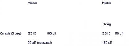
If I have correctly interpreted your test as depicted in the left diagram below, I agree that the reflections of the house should affect the 0 and 180 degree readings equally, assuming the house is perpendicular to the measurement positions.
If the house main axis is not perpendicular (or the house not symmetrical) to the measurement, 0 degree, and 180 degree positions, the reflected wave would have a different SPL at each position.
If that is the case, swapping the 0 and 180 positions would result in slightly different measured results.
The inverse square law has interesting consequences.
It takes 120 dB at one meter to make 100 dB at 10 meters.
At 80 meters, (more than the distance of the reflected wave from the house to the 90 degree position) the level of the reflected wave off a large house could still be as much as 82 dB, less additional loss than the difference from 1 meter to 10 meters.
Orientation is important, if the directivity test were conducted as laid out on the right, different results from what you measured would be read.
Art
Attachments
posting and interesting link about directivity while integrating speakers. It's very illustrative.
Loudspeaker Facts - Directivity as a Design Issue -page 2
Loudspeaker Facts - Directivity as a Design Issue -page 2
Hello
We have a club that has some tapped horns in it, the room is not big, when we put the horns in the corners to have more low freq response and also make more room for the dance floor, the part where dj is (between the subs) has more low freq coverage than the dancefloor, thus making it very hard to dj for a longer period of time because of the SPL.

When we put the subs away from the corners, on each side of the table, then the situation changes, everything is fine on both ends.

Could it be somehow possible to fix this while having subs in the corners? Maybe add a waveguide for the subs, like mentioned here?
August
We have a club that has some tapped horns in it, the room is not big, when we put the horns in the corners to have more low freq response and also make more room for the dance floor, the part where dj is (between the subs) has more low freq coverage than the dancefloor, thus making it very hard to dj for a longer period of time because of the SPL.
When we put the subs away from the corners, on each side of the table, then the situation changes, everything is fine on both ends.
Could it be somehow possible to fix this while having subs in the corners? Maybe add a waveguide for the subs, like mentioned here?
August
August,Hello
We have a club that has some tapped horns in it, the room is not big, when we put the horns in the corners to have more low freq response and also make more room for the dance floor, the part where dj is (between the subs) has more low freq coverage than the dancefloor, thus making it very hard to dj for a longer period of time because of the SPL.
When we put the subs away from the corners, on each side of the table, then the situation changes, everything is fine on both ends.
Could it be somehow possible to fix this while having subs in the corners? Maybe add a waveguide for the subs, like mentioned here?
Sounds like the problem is due to the room dimensions and sub location. Waveguides would not correct the low frequency problem, but could possibly help in the upper bass range.
Moving the subs and DJ to the shorter wall dimension may have better results than your present set up.
Art
What are the room dimensions? With those, you can simulate what positions are relatively silent.
If the problem is the second axial mode between left and right wall, it has a pressure node (silence) at 1/4 from either wall. So you could try moving the DJ a bit to the left or right such that he is at 1/4 or 3/4 between these walls.
The same applies to the front / rear direction, though putting a DJ at 1/4 (front to rear) wall spacing away from the rear wall might be impractical.
Last edited:


- Status
- This old topic is closed. If you want to reopen this topic, contact a moderator using the "Report Post" button.
- Home
- Loudspeakers
- Subwoofers
- Tapped Horn Directivity