Driver specs PDF says 13.64.
I would have used the spec sheet number but of late many a PE pdf shows blank... Acrobat gives an error message about an encryption dictionary.
dave
Help me out with these equations from http://www.quarter-wave.com/Back_Door/T_S_Consistency_Check_Vad.pdf to calc BL cause I'm getting way off results with T/S params given in the drawings above and the constants for air density and sound velocity in the PDF.
For example, Vad = 85.1 L, p = 1.205 kg/m^-3, c = 344 m/s^-1, Sd = 515 cm^2, Fd = 25 Hz, and Qed = 3.12.
To get BL we need to find Cmd m/N to get Mmd grams.
So Cmd = Vad *(ρ*c*c*Sd*Sd) ^-1
thus:
= 85.1 * (1.205 * 344 * 344 * 515 * 515 ) ^-1
= 85.1 * (37,819,727,048) ^-1
= 85.1 * 2.64 x 10^-11
= 2.25 * 10^-9 m/N This is 10,000 times smaller than the example of 9.45 * 10^-4
and Mmd grams = (Cmd * fd * fd) ^-1
thus:
= (2.25 * 10^-9 * 25Hz * 25Hz) ^-1
= (1.406 * 10^-6) ^-1
= 711,064 grams Ummm... that's 711 Kilograms! not just a few grams.
and finally, BL telsa-meters = ((fd * Re * Mmd) / Qed) ^0.5
thus:
= ((25 * 4 ohms * 711,064)/3.12) ^0.5
= ((71,106,400/3.12) ^0.5
= (22,790,512) ^0.5
= 4,774 telsa-meters
Ummm... this can't be correct! Example given of 6.4 Tm is 745 times less. Wherein did I go wrong?
.
I'm pretty sure your mistake is in your Sd. You need to use m^2, not cm^2. 515 cm^2=0.0515 m^2.
Notice how you're off by a factor of 10,000 and 1m^2 = 10,000 cm^2.
")
Last edited:
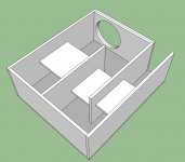
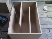
I think those battens can't do any harm but Dave is your man here, what does he think? I am guessing you can run them slightly offset from the center of each to reduce the exciting. Dave?
For what is there, they are the correct orientation. They'd be much more effective if they reached all the way across to the other side (with lots of holes). They should be off-centre,
dave
That must be it, Oscar! However, the PDF of King's equations specifically says Sd is in sq cm, and the value was not fractional, thus not a typo. But, since all the units are based on meters, it must be a typo or a grand assumption that those looking at should know to use sq meters instead.I'm pretty sure your mistake is in your Sd. You need to use m^2, not cm^2. 515 cm^2=0.0515 m^2.
So, using 0.515 for Sd, BL = 4.7 Tm, which is 68% less than the mfr spec of 13.64. Oh well... it was a fun exercise.
Thanks.
However, the PDF of King's equations specifically says Sd is in sq cm, and the value was not fractional, thus not a typo. But, since all the units are based on meters, it must be a typo or a grand assumption that those looking at should know to use sq meters instead.
With respect to the T/S calculations, MathCad takes whatever units you input and automatically converts them to a consistent set of MKS units. For example. you can enter Sd in m^2, cm^2, ft^2, in^2, or any other convenient area unit and the answers will be the same. That is why there are no constant terms in any of the equations used to calculate the T/S parameters. Doing the calculations by hand you have to make sure your units are consistent and double check the final units of the value calculated. Eliminating the units hassle is one of the great properties of MathCad and prevents a ton of mistakes.
However, the Excel spreadsheet based on the alignment tables is unit sensitive so you have to input the values with the units shown. Any hand calculations done based on the alignment tables are also unit sensitive.
Martin
Last edited:
Thanks for joining the convo, Martin. I don't have the spreadsheets as they're not free and was seeing if I could use the equations in the similarly titled PDFs on your website to calc the driver BL. Then I discovered it was in the driver spec sheet after all.MathCad takes whatever units you input and automatically converts them to a consistent set of MKS units.
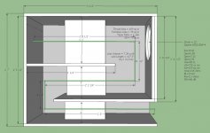
Since you're the expert, do you see any other flaws or issues with my first attempt at designing a Tline sub (latest below w/driver 28% down line)?
Is Dz in the free XLS spreadsheet (screen shots on page 2) the proper variable name for driver offset down from the closed end?
Dean
.
Attachments
Last edited:
Since you're the expert, do you see any other flaws or issues with my first attempt at designing a Tline sub (latest below w/driver 28% down line)?
Is Dz in the free XLS spreadsheet (screen shots on page 2) the proper variable name for driver offset down from the closed end?
Without running detailed simulations I cannot really comment on your design. The simulations run early in the thread are what you should rerun to assess the current version of your design.
The variables Dz and Dr in the spreadsheet are not physical dimensions or properties of the transmission line. They are factors used to lump many parameters to keep the alignment tables simple and reproducing the target SPL response. If you read the documention you will find where they fit into the scheme of the alignment tables. They are echoed in the spreadsheet to allow the user to double check the results against any hand calculations.
Martin
- Status
- This old topic is closed. If you want to reopen this topic, contact a moderator using the "Report Post" button.
- Home
- Loudspeakers
- Subwoofers
- Critique this Tline