Nobody wants failures and that’s the reason why I am looking for a method that gives the maximum and safe power input for a driver in a tapped horn. But after exchanging our information I have come to the conclusion that there is no wrong and right here.
Both methods are theoretical and have both their advantages and disadvantages. Both methods do not take into account that in real life situations the result is lower excursions!
I have measured actual displacement on many BR alignments, they were as close to the simulations as I could possibly expect, holding and reading a ruler while in a 130+ dB sound field.
I have measured excursion on several tapped horns, but have not yet simulated them, so can't say how they compare.
I hope to eventually, finally got on a Windows machine and started playing with Hornresp.
Have you found actual ('real life") excursion readings to be less than predicted , and if so, could you give an example ?
Art
I don't like the simplifications, magnet structures vary too much, and it's easy to do the math.
An example of your method failure is the Eminence sold by Martinsound as the #1844. It has 9.1mm x-max, but the top plate is only 7.93mm. By your method the 50% BL point should be 12.74mm. The 9.1mm is with the 70% BL method, so the 50% BL point would only be 11mm.
Maybe I just like being cautious.
Don’t get me wrong here Djk cause you are right from a theoretical point of view. The variables show to many differentiations to melt them into such simplistic representation.
But why don’t you like this specific simplification and in the same time you ask and use Xmax numbers in previous posts while all brands use different methods to get the Xmax number? There is a bigger tolerance in that Xmax then in my simplification, I think.
Xmax formulas as used by different brands:
(Hvc – Hg)/2 + unknown variable (B&C)
(Hvc - Hg)/2 + Hg/4 (RCF and 18Sound)
(Hvc - Hg)/2 + Hg/3.5 (Beyma)
(Hvc - Hg)/2 (Eminence)
Please don't get me wrong here since I do respect you and I'm very pleased with your look on all these matters. All what I try to say here, isn't simplification sometimes a very practical tool to overcome endless details with acceptable tolerances?
I think in relative 'fast' comparisons we do around here it would be very handy to use some sort of 'quick' method that even will work in the real world. In case of improving designs to the fullest I totally agree to dig into the smallest details.
Btw I'm working on some sort of quick formula that will integrate BL, Xmax and Xlim...
Last edited:
I have measured actual displacement on many BR alignments, they were as close to the simulations as I could possibly expect, holding and reading a ruler while in a 130+ dB sound field.
I have measured excursion on several tapped horns, but have not yet simulated them, so can't say how they compare.
I hope to eventually, finally got on a Windows machine and started playing with Hornresp.
Have you found actual ('real life") excursion readings to be less than predicted , and if so, could you give an example ?
Art
Good point there Art, nope in my tests from September with the Tham I haven’t measured its excursion. Non of my friends did as far I know (I’ll ask this week). All I know about excursion comes from 3th parties and my own eye observations for what it’s worth. I saw unexpected low excursions at Xmax levels (build an old Fane horn concept with a plexiglass window and you see the difference). That’s why I was starting to ‘feed’ it way above the Xmax predictions without noticing anything funny, well at some point it did as the SPL wouldn't rise any longer. Throughout the tests, and that made me think, I noticed lower temperatures then I expected at these volumes (these 18sounds 15LW1401’s can get serious hot in some cabs).
Hi Djim,
In Post #162 you say: "...I'm working on some sort of quick formula that will integrate BL, Xmax and Xlim...".
I find the general line of thought quite interesting, but, you are looking for a formula that combines three variables that are not related except by the accident that they reside within the same transducer.
It's just not very plausible.
Regards,
Sorry TB, cause it wasn’t meant as you can read it (remember I'm Dutch") ). I meant I’m looking for a formula that integrates BL and Xmax and I will polish my Xlim formula as I found exceptions for that also.
). I meant I’m looking for a formula that integrates BL and Xmax and I will polish my Xlim formula as I found exceptions for that also.
But thanks Oliver for notifying, cause I wouldn't have seen it (cause I 'work' at ridiculous hours as you can see)
). I meant I’m looking for a formula that integrates BL and Xmax and I will polish my Xlim formula as I found exceptions for that also. But thanks Oliver for notifying, cause I wouldn't have seen it (cause I 'work' at ridiculous hours as you can see)
Last edited:
the problem is that different manufacteres us different methodes,on the x-max ratings.Sorry TB, cause it wasn’t meant as you can read it (remember I'm Dutch
But thanks Oliver for notifying, cause I wouldn't have seen it (cause I 'work' at ridiculous hours as you can see)
some use 10% distrtion point ,some 70% bl some use liniar.
also magnetic field always extends a bit out of the gap.
i think personal experience with a type of woofer (like your example of the plexy bin) gives a good indication how far you can push it.
the problem is that different manufacteres us different methodes,on the x-max ratings.
some use 10% distrtion point ,some 70% bl some use liniar.
also magnetic field always extends a bit out of the gap.
i think personal experience with a type of woofer (like your example of the plexy bin) gives a good indication how far you can push it.
Yes, there is all sort of formulas, but what i use is simple formula of voice coil winding height - air gap height and then divided by two. That gives Xmax within 82% BL rating and that is commonly considered as limit.
Power handling is then completely different issue.
I was pointed out by Djk that the Max Pwr Input method for PA drivers in TH’s wasn’t accurate enough (and this could lead to damaging the driver in some cases). His example of the Martin Sound #1844 driver was to show me it is necessary to reconsider the formula. I only used the Xmax tolerances as an example of how we seem to accept certain tolerances.
1.) However, the question here is about how much tolerance within the Max Pwr method is acceptable?
I could spend time trying to build a method that is more accurate by integrating the BL factor (which makes the method a little more complex) or I could use the method as it is and give limitations to the driver’s BL factor. For example drivers with a BL factor between 20 and 30Tm.
2.) Now my second question is, will the integration of a BL factor deliver accurate results enough, in other words, within acceptable tolerances?
Okay, I have a new formula for Max efficient Excursions (BL50%) for PA bass drivers in Tapped Horns.
The formula is getting a little more complex but still doesn't need anything more then BL and Xmax data of the driver.
The new formula uses a new approach. It also includes the extra field force outside the magnet gap that will be stronger with the rise of the BL factor. This extra correction is a very low 'cautious' factor at this stage because I haven’t found solid information about the force field outside the gap. In future this number may rise in case I can get the info I’m looking for (hint hint hint).
M.E.E. method V2:
(BL x 0,017) + 0,9 = BLc
BLc x Xmax = Max Efficient Excursion (BL50%)
Or:
[(BL x 0,017) + 0,9] x Xmax = Max Efficient Excursion (BL50%)
Hi
I see that the discussion moved to the more delicate things, but I have an interest in finding a folding of a horn with a given exterior dimensions.
I want to play between 30 and 100 hertz, use 18mm plywood, and use it in pairs or more.
The ratio is one to two on the front and it offers various ways to stack the boxes. Subwoofer I want is 21sw115, but it is not forced.
The dimensions are 60 by 80 by 120 centimeters. (24 31,5 48 inches)
Which folding would you suggest to get the most out of these dimensions?
For a TH, the folding scheme of the Apache MK 2, Screamer's Fury, or Jbell's Stadium all are viable, if made long enough to do 30 Hz .Hi
I see that the discussion moved to the more delicate things, but I have an interest in finding a folding of a horn with a given exterior dimensions.
I want to play between 30 and 100 hertz, use 18mm plywood, and use it in pairs or more.
The ratio is one to two on the front and it offers various ways to stack the boxes. Subwoofer I want is 21sw115, but it is not forced.
The dimensions are 60 by 80 by 120 centimeters. (24 31,5 48 inches)
Which folding would you suggest to get the most out of these dimensions?
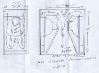
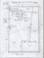
If you could go to a 24 x 45 x 45 inch ( I'd avoid 48 inch unless using wide body semi trucks ) size you could use something like the FLH diagram I just scratched out. The 21SW115 is a rather deep speaker, it would be a squeeze.
You could also use my B- Low Rider design, it gets down pretty well flat to the Low B (32 Hz) using Peavey low rider 15s, a very good inexpensive speaker. It is a 2 x 15 design, but a 21" looks like it would almost fit.
Attachments
Last edited:
Some clarifications are in order regarding the TH-118 specifications.Going with the DSL TH-118 (loaded with a B&C 18SW115-4) as a benchmark, it is 101 dB one watt one meter at 30 Hz.
Assuming the driver would stay under Xmax at 4000 watts, that would put the 30 Hz peak output for a single at 127 dB.
Add 12 dB for four, 139 dB at 30 Hz with 16,000 watts.
My meat computer says they will flap at less than half that power at 30Hz (below the driver’s Fs), I think 136 dB might just happen, but would still exceed Xmax.
Ordered a pair of B&C 18SW115-4 from Pro Sound Service yesterday, shipped this morning.
My build will probably be 26.5” by 22.5” x 45” tall cabinets, slightly more volume than the TH-118.
Art
The four ohm TH-118 was tested at 28.3 volts ( about 200, not 100 watts), there was a copy and paste error in the spec sheet. It may be a 18NLW9600-4 rather than the BC18SW115-4, the first TH-118s used the 18 sound speakers.
The equivalent one watt one meter level is actually 98 dB at 30 Hz, 102 dB at 40 Hz.
I have done a Hornresp sim in a TH box of the approximate dimensions described above using the BC18SW115-4, it shows 130 dB at 40 Hz and 125 dB at 30 Hz with 60 V (800 watt) input, maximum excursion looks to be about 13 mm, the rated Xmax is 14 mm.
Hornresp predicts four speakers at 137 dB at 30 Hz, 139 at 40 Hz with 60 V (3200w total between 4 speakers) applied.
Still misses the 140 dB at 30 Hz goal, but if one does not mind more a bit more than 10% distortion, another 3 dB input would reach it.
I applied a 50 volt, 11 Hz sine wave (about 160 watts each) to a series pair of the BC18SW115-4 for two hours yesterday to loosen up the suspension.
Open air, they still did not exceed the Xmax figure, they started at about 25 mm peak to peak, and were at 27 mm two hours later. Break in does not seem to do much.
The suspensions were amazingly quiet at that excursion, less noise than the amplifier fan.
The amplifier fan output seemed much warmer than the speaker vents. The magnet structures only felt a few degrees above ambient temperature.
Also did a quick test at about 55 V into a single, about 750 watts open air.
Didn’t get an accurate excursion measurement as I swept down from 60 Hz, the speaker walks around quite a bit at certain frequencies, it hopped off the speaker cords it was sitting on, which had kept the vent open during the 2 hour break in.
As a rough guess there was around 30 mm peak to peak down at 10 Hz, still hardly exceeding Xmax.
There was a bit of adhesive smell after about 10 seconds of that test.
It would take many horsepower to get the speaker to exceed it’s 60 mm peak to peak Xlim rating.
Art
Last edited:
Post #171
Hi weltersys,
I'm happy that somebody takes up the bifurcated throat coupling that DSL used in their DTS-20. It is way underutilized. I had it in my guess on how one may fold enough horn into the space of the TH-115, but was told that what I had there was just too difficult to build. Probably a valid complaint as I carried the bifurcation around a 90 degree bend, yours looks just fine to me.
As you are now experimenting with Hornresp you may try to couple the driver to the throat through a throat chamber and a coupling duct (e.g.: 6"Dia. 1.5"-20"long) into the horn throat (S1=S2, L12=0.1"). I have on paper produced tapped horns w/ an amazingly wide frequency response, especially in groups of four. This design changes the driver loading quite substantially, the only question is the restriction at high volume levels.
Regards,
hi henkoHi
I see that the discussion moved to the more delicate things, but I have an interest in finding a folding of a horn with a given exterior dimensions.
I want to play between 30 and 100 hertz, use 18mm plywood, and use it in pairs or more.
The ratio is one to two on the front and it offers various ways to stack the boxes. Subwoofer I want is 21sw115, but it is not forced.
The dimensions are 60 by 80 by 120 centimeters. (24 31,5 48 inches)
Which folding would you suggest to get the most out of these dimensions?
do you want a front loaded horn or a tapped horn?
i think a tapped horn is posseble in those dimensions.
for a flh i think it might be 2 small ,but i give it a try if you want
edit/ with a th you get 141 db with 4 32hz>100hz ,-3db@28 @ x-max 14
Last edited:
The "bifurcated throat coupling" goes back as far as I can remember, just another folding trick that works well when the extra depth of wood in a "normal" zig zag won't work due to various restraints. The wood can add up to a lot of internal space, the smaller the cabinet, the worse the effect.Hi weltersys,
I'm happy that somebody takes up the bifurcated throat coupling that DSL used in their DTS-20. It is way underutilized. I had it in my guess on how one may fold enough horn into the space of the TH-115, but was told that what I had there was just too difficult to build. Probably a valid complaint as I carried the bifurcation around a 90 degree bend, yours looks just fine to me.
As you are now experimenting with Hornresp you may try to couple the driver to the throat through a throat chamber and a coupling duct (e.g.: 6"Dia. 1.5"-20"long) into the horn throat (S1=S2, L12=0.1"). I have on paper produced tapped horns w/ an amazingly wide frequency response, especially in groups of four. This design changes the driver loading quite substantially, the only question is the restriction at high volume levels.
Regards,
Thinner wood would help, but 3/4" is the minimum I'd consider with over 3 horsepower input.
I have been using a throat duct in my sims, in fact just figured out the actual volume in front of the BC18SW115 cone, it is a big deep cone, the "flat piston" assumed by Hornresp ignores that area and the cabinet's baffle wall thickness.
With the speaker on a 3/4" baffle, that enclosed volume is around 7.685 liters, .27 cubic feet, before any ducting is employed, the volume of a small ported enclosure!
Hi weltersys,
Hornresp provides the ability to enter the throat chamber, its cross-section and the chamber opening/coupling duct under Ap1/Lpt/Vtc/Atc.
Regards,
Yes, I was aware of that, but until this morning when I poured elbow macaroni from a 250ML cup into the cone to figure out the volume, did not have more than a rough estimate of the numbers to enter. I should have used water, the cone is treated, and I ran out of macaroni at 1750ml so still had to do the math.
I'm getting better at visualizing centimeters vs. inches, but still "challenged" thinking in metric volumes
.i measured a 18"cone once,and it was aprox 6 ltrs,an a total of 8 with neo magnetYes, I was aware of that, but until this morning when I poured elbow macaroni from a 250ML cup into the cone to figure out the volume, did not have more than a rough estimate of the numbers to enter. I should have used water, the cone is treated, and I ran out of macaroni at 1750ml so still had to do the math.
I'm getting better at visualizing centimeters vs. inches, but still "challenged" thinking in metric volumes
- Home
- Loudspeakers
- Subwoofers
- C/E/X PA Flat to 30 (FT30) PA TH Awesomeness